
IR Remote Control Extender mark 4 Circuit
The infrared wired repeater circuit serves as an interface for controlling various electrical appliances from a distance, utilizing infrared signals for communication. This circuit typically consists of several key components, including resistors, an infrared receiver, an infrared transmitter, and possibly additional supporting components like capacitors and diodes.
The resistors listed in the parts list, R1 (1kΩ), R2 (3.3kΩ), and R3 (10kΩ), are used to limit current and set the appropriate voltage levels within the circuit. R1 might be used in conjunction with the infrared receiver to ensure that the input signal is at a safe level for processing. R2 could serve as a pull-up resistor for the output signal, ensuring that the line is high when the infrared signal is not being received. R3 may be part of a voltage divider or biasing network for the infrared transmitter, allowing it to function efficiently when sending signals to the controlled appliances.
The infrared receiver detects signals from a remote control device, converting these signals into electrical impulses. The output from the receiver is then processed by the circuit, which may include a microcontroller or a simple transistor switch to activate the infrared transmitter. The transmitter, in turn, sends the appropriate infrared signals to the targeted appliances, effectively allowing remote control functionality.
To enhance the circuit's performance, additional components such as capacitors may be included to filter out noise and stabilize the power supply. Diodes could be used for protection against reverse polarity or to ensure that current flows in the correct direction.
Overall, this infrared wired repeater circuit is a practical solution for remote appliance control, providing convenience and flexibility in managing electronic devices from various locations within a home or office environment.An Infra Red wired Repeater circuit to control appliances from a remote location. Parts List: R1: 1k Resistor (1) R2: 3.3k Resistor (1) R3: 10k. 🔗 External reference
Related Circuits
The Project Long Range Remote Control can be used to remotely control a number of Electrical or Electronic Gadgets connected to it. Unlike Infra Red remote control, this Project employs FM transmission and Reception, and hence it can be...
This is a simple flyback tester circuit designed to test high-frequency transformers, such as those used in switch-mode power supplies (SMPS) or flyback transformers. The circuit operates as an astable multivibrator with a frequency of approximately 90 kHz, powered...
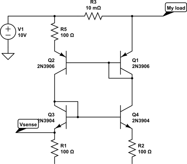
The bases and emitters of the transistors are connected together, resulting in equal base-emitter voltages. Assuming the transistors are identical, equal Vbe leads to equal base currents, which in turn results in equal collector-emitter currents. By adjusting the voltage...
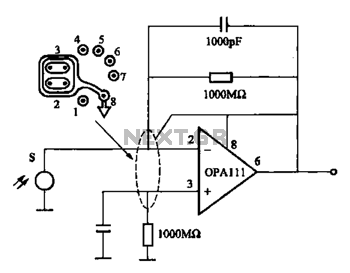
Infrared heat is emitted by an object during non-contact temperature measurement. The measured signal is weak, necessitating the use of highly sensitive thermal infrared sensors with minimal noise. Consequently, the amplifier circuit must also meet stringent requirements, as standard...
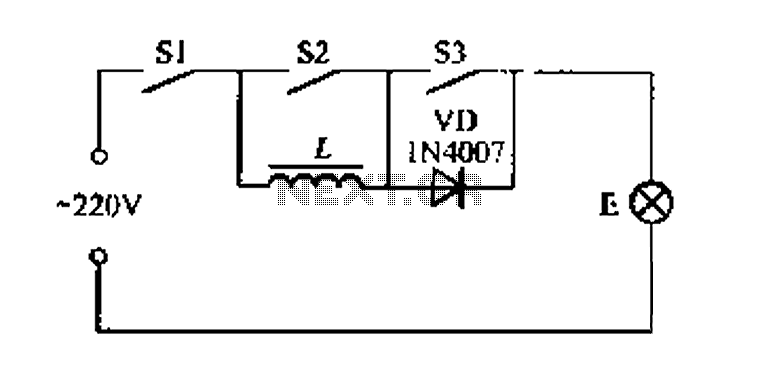
A portable four dimmer switch circuit is illustrated in Figure 8, featuring a four-speed brightness adjustment. When switches S1, S2, and S3 are all closed, the lamp operates at its brightest setting. When S1 and S2 are closed while...
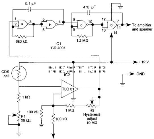
The TL081 is utilized as a comparator within a Wheatstone bridge circuit. When the resistance of the CDS cell decreases due to light exposure, the output from IC2 prompts the low-frequency oscillators (a) and (b) to produce a 10-Hz...