
Transistor current mirror circuit
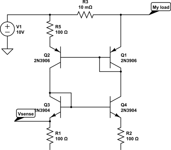
The described circuit employs a configuration of transistors where the bases and emitters are interconnected, ensuring that the base-emitter voltages (Vbe) remain consistent across the devices. This arrangement is crucial for maintaining equal currents flowing through the base and subsequently through the collector-emitter paths of the transistors. The principle of current mirroring is applied here, which is fundamental in various analog applications, including overcurrent protection systems.
To implement an overcurrent detection mechanism, a secondary resistor can be introduced in the mirrored leg of the circuit. The voltage drop across this resistor is monitored; if it exceeds a specified threshold, it indicates that the current flowing through the circuit has surpassed the safe operating limit. This method allows for a precise measurement of the current without directly interfering with the primary circuit operation.
Alternatively, the circuit can be simplified by placing a shunt resistor in the primary leg, which provides a direct measurement of the current flowing through the supply. This alternative method is often preferred due to its straightforward implementation and effectiveness in providing accurate current readings.
Current mirrors are particularly advantageous in high-side applications where the load is connected to a positive supply voltage. By using PNP transistors in the current mirror configuration, the circuit can reference the ground voltage, making it easier to monitor the load current. The secondary load is connected between the collector of the secondary transistor and ground, allowing for a proportional voltage signal that reflects the load current. This configuration enhances the reliability of the overcurrent protection system by ensuring that the voltage reference remains stable and accurately reflects the operating conditions.
The gain of the circuit can be adjusted by varying the resistor values, allowing for fine-tuning of the sensitivity and response of the overcurrent detection mechanism. This flexibility is essential for adapting the circuit to different applications and ensuring optimal performance in various operating environments. Overall, the described circuit provides a robust solution for monitoring and protecting against overcurrent conditions in electronic systems.The bases and emitters are tied together, so the base-emitter voltages are equal. Since we assume the transistors themselves are identical, equal Vbe means equal current into the base. And equal current into the base means equal current from collector to emitter. Thus by setting the current through one, by the selection of voltage and resistance, you also set the current through the other. One way of doing an overcurrent detector would be to put a second resistor in the mirrored leg, and measure the voltage across that resistor. If it rises above some fixed level, the current must have exceeded your setpoint. I`m not immediately sure why that would be better than measuring the voltage on the primary leg, though.
At first glance, this seems like a pretty round-about way of doing an overcurrent limit. Thanks Remiel. I have a supply and the load between which this circuit is connected to monitor the safe current that is sourced by the supply. So I need to use this circuit to detect the over current drawn from the supply. So is there anyway that i can do with this Durgaprasad Mar 20 `13 at 17:02 Yes, you could put a resistor between the secondary source and the secondary transistor, and measure the voltage across that resistor.
But again, a shunt resistor in the primary would be simpler and should have nearly identical effect. Stephen Collings Mar 20 `13 at 18:21 Current mirrors are often used in overcurrent protection because it allows a shift of the voltage reference from Vin to Gnd. Use a high-side current mirror (PNP transistors instead of NPN) and put the "secondary load" between the collector of the secondary transistor and ground.
Now you have a ground-referenced voltage that`s proportional to the high-side load current. Note that the value of the resistor can be varied to determine the "gain" of the circuit. 🔗 External reference
Related Circuits
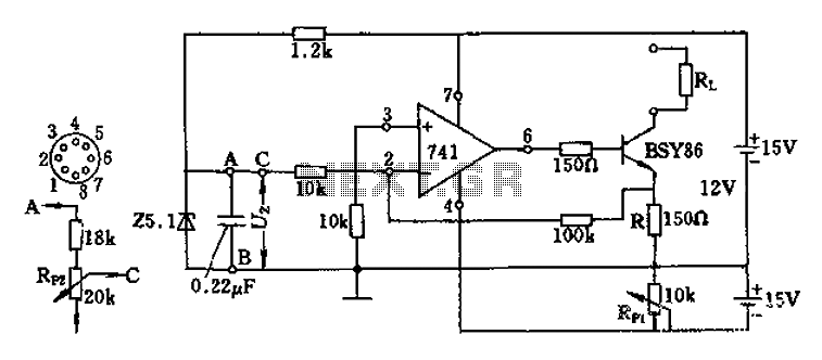
The Darlington transistor circuit BSY86 produces a large output current, with a maximum limit of 150 ohms. The output current is adjustable via resistor R and the RP1 potentiometer, maintaining constancy regardless of the load resistance Rl. The potentiometer...
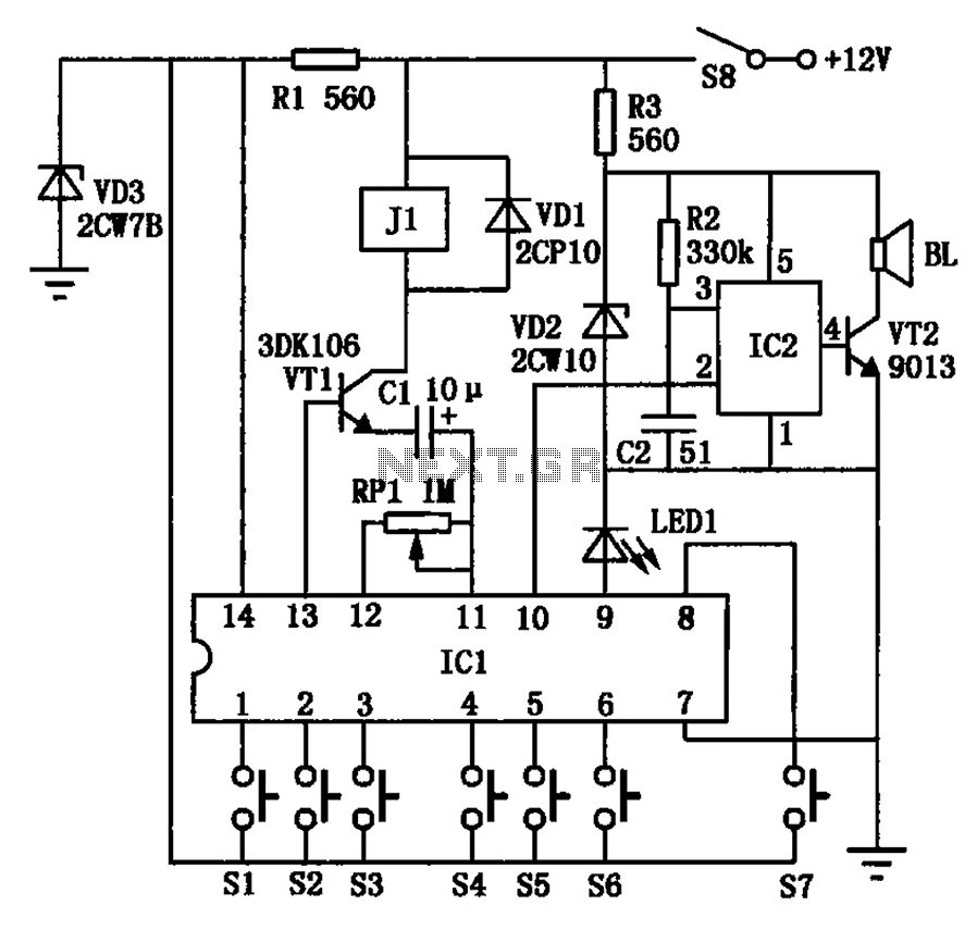
The automotive electronic locks circuit principle is illustrated with the dedicated lock IC 5G058. It features an external key switch connected to the positive power supply. The circuit includes six valid input keys, unlock keys S1 to S6, which...
This circuit allows the use of an inexpensive loudspeaker as a microphone. Sound waves that reach the speaker cone create fluctuations in the voice coil. The movement of the voice coil within the speaker's magnetic field generates a small...

This circuit design is for a high current toggle switch, adapted from the "Toggle Switch Debounced Pushbutton" by John Lundgren. It is intended for applications where the load needs to be switched on from one location and off from...
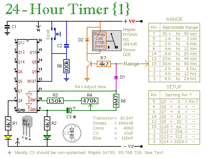
A pair of multi-range timers that provide timing periods extending up to 24 hours and beyond. Both timers are fundamentally identical, with the primary distinction being their relay behavior upon the completion of the timing cycle. Version 1 activates...
A MOSFET is employed to drive a load that includes a sense resistor in its current path. The voltage across this resistor is utilized to trigger a circuit capable of disconnecting the load in the event of an overcurrent...