
ir remote control extender mark 5
The major issue addressed in the Mark 5 circuit is the separation of ambient light from the modulated light emitted by remote handsets. The previous Mark 1 circuit was overly sensitive to all light sources, causing the IR photodiode to produce a continuous signal that was amplified by the rest of the circuit. The solution implemented in the Mark 5 involves a simple RC filter formed by capacitor C1 and resistor R3. At low frequencies, such as 50 Hz, the impedance of C1 is high (approximately 144 kΩ), leading to a gain of less than unity. Conversely, the IR signal from a remote handset is modulated at around 36 kHz, where the impedance of C1 drops significantly (around 200 Ω), allowing for a voltage gain of approximately 34 times.
The circuit employs an IR photodiode, specifically the SFH2030, which can be replaced with a SFH2030F that includes a daylight filter. The photodiode is reverse-biased, and when IR light strikes it, charge carriers are released, resulting in increased current flow. This current is amplified and converted to a voltage by the first CA3140 operational amplifier (IC1), configured as a current-to-voltage converter. The output voltage at pin 6 of IC1 is approximately 5.6 V/µA, generated from the currents produced by the photodiode when receiving signals from a remote control several meters away. The circuit requires high input impedance to prevent signal shunting, which is why the CA3140 is chosen due to its input impedance exceeding 1000 GΩ.
The design also incorporates noise rejection strategies, utilizing the impedance of capacitor C4 to allow higher frequency signals to pass while attenuating lower frequency noise. This careful design ensures that the Mark 5 circuit effectively differentiates between steady ambient light and modulated IR signals, providing reliable operation in various lighting conditions. The Mark 5 represents a significant advancement in IR repeater technology, ensuring compatibility with a wide range of remote control handsets while maintaining robust performance against interference.The latest addition to my collection of Infra Red (IR) Repeater circuits. The Mark 5 is a much improved version of the Mark 1 circuit and has increased range and sensitivity. It is also immune to the effects ofambient light, daylight and other forms of interference. In addition it works with IR modulation freuencies in the range 30 to 120kHz makin g the Mk5 circuit the best choice for compatibility with remote controls. This time I have returned to "first principles" and built a wideband infra red (IR) preamp which receives and re-transmits the entire baseband signal from a remote control handset. It is designed to work with IR controls using 30-120KHz and should therefore work with just about any handset.
In addition I have separated ambient (surrounding) light from the modulated light used by a remote handset. The major problem with the Mark 1 circuit is that it reacts to all light sources, ambient light producing a continous signal from the IR photo diode and is amplified by the rest of the circuit.
I have published a modification to the original Mark 1 circuit, click here to view. It is difficult working with Infra Red, you cannot see it, and it is difficult to measure. A major barrier with this circuit was how to differentiate between daylight and an IR signal. Ambient light produces an almost continuous signal, changing little over several hours. A signal from an IR handset contains control pulses modulated with a carrier frequency (typically 36kHz) transmitted using an Infra Red photo diode. My solution used here, is a simple RC filter formed by C1 and R3. At low frequency i. e. 50Hz the impedance of C1 is high, around 144k. The voltage gain of inverting op-amp IC2 is approximately R4 / R3, but at low frequency C1 is in series with R3 so the gain is now 120k / (3.
3k + 144k) or less than unity. Daylight or ambient light will change slowly over several hours, in frequency terms this signal would be millihertz or less and C1`s impedance will be megaohms. A signal from an IR handset will be modulated at around 36KHz. At this frequency the impedance of C1 is very low, around 200 ohms. This has little effect on the input impedance of the op-amp stage and voltage gain will now be R4 / R3 or about 34 times.
The impedance of capacitor C4 also helps noise rejection as its impedance change will allow more signal to pass into Q1 base at high frequencies and much less signal at line frequencies. Light photons are received at IR1, this is an IR photo diode type SFH2030. A SFH2030F, which contains a daylight filter, may also be used instead of the SFH2030. The photo diode is reverse biased and when light strikes it, the energy of the IR signal releases additional charge carriers within the diode, allowing more current to flow.
This current is amplified and converted to a voltage by the first CA3140 opamp, IC1. IC1 is wired as a current to voltage convertor, see below. In an ideal current to voltage convertor the output voltage would be the product Rf multiplied by the input current. The non-inverting input would be tied to ground. In the Mark 5 circuit the output voltage is iR1 or about 5. 6 Volts/uA appearing at pin 6 of IC1. The current generated by the SFH2030 photo diode when receiving a signal from a handset several metres away is less than 50 nA and requires the extreme high input impedance to avoid shunting the signal.
There are two reasons for using the CA3140, the first is its high input impedance, over 1000G. The second reason is that normally the non-inverting input would be at 0V when working from split + and - supplies. In this single supply version the non-inverting input is returned to negative supply via R2. This can only be done with a Mosfet input, hence the choice for using the CA3140. IC1 converta all current from the photo diode IR1 into a voltage. Although the SFH2030 is most sensitive at infra red wavelengths, it will produce tiny currents from dayl
🔗 External reference
Related Circuits
Microcontroller-based water tank filler circuit diagram. Differences between microprocessors and microcontrollers, parallel port interfacing projects using microcontrollers, applications of microcontrollers in real life, circuit diagram of AVR microcontroller trainer, 8086 microcontroller, microcontroller-based drip irrigation system circuit, design of pulse...
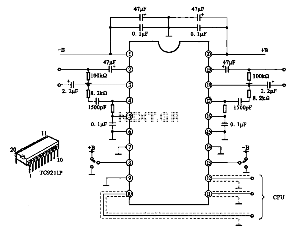
A typical electronic volume control circuit is commonly used in stereo audio devices connected through a computer (CPU). The circuit adjusts the volume of stereo signals via input and output pins. Control signals are sent to the CPU (including...
The circuit is straightforward and cost-effective. This is advantageous since most commercially available stepper motor controller ICs tend to be quite pricey. It is constructed using standard components and can be easily modified for computer control. By utilizing inexpensive...
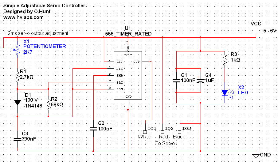
The circuit is straightforward. A 555 timer integrated circuit (IC) is utilized to generate a pulse every 20 milliseconds, with a duty cycle ranging from 5% to 10% (1-2 milliseconds). All components used are standard parts. This circuit can...
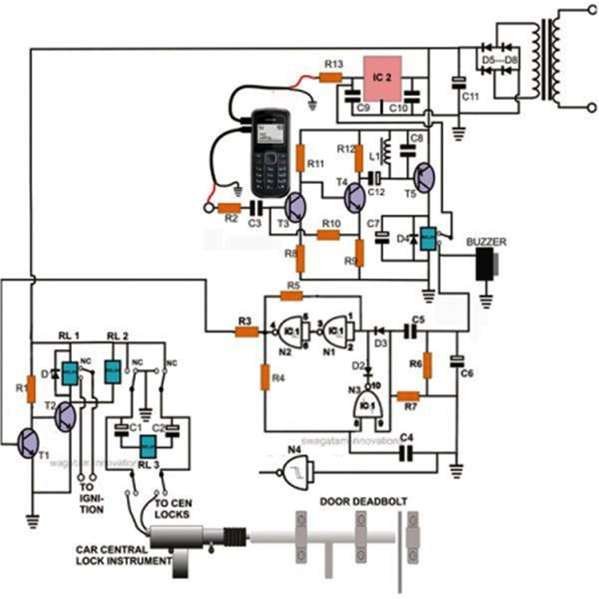
Controlling a door lock through a personal cell phone has become remarkably straightforward. This project outlines the construction of a simple electronic circuit that transforms a conventional door lock into a high-security lock, which can now be operated via...
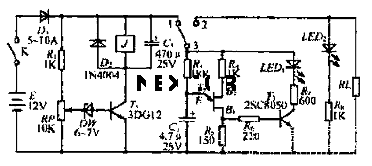
The discharge control circuit consists of a battery management system designed to prevent over-discharge of a battery. It features a relay control mechanism that activates when the battery voltage drops below a specified threshold of approximately 10.5V. The circuit...