
IR remote control for PC
This gated signal is then used to drive the IR LED via the driver section. The IR LED driver section consists of a 7405 hex open-collector buffer. All the outputs of the 7405 are tied together to give enough current to drive the IR LED. The two 1N4001 diodes are used to step down the voltage to around 3V for the IR LED. This may seem as an overkill but you can drive several IR LED's simultaneously.
The 555 frequency can be adjusted for remote controls whose carrier frequency varies from the standard 40Khz.
The record/playback software can be obtained free of charge from GKDesign. Please email us to get a copy of the executable and source code. The software allows you to record/playback and view any IR remote control signal. The real fun begins when you write your own software to control your house. For example, a program can be easily written that automatically programs the clock on your VCR, TV and anything else.
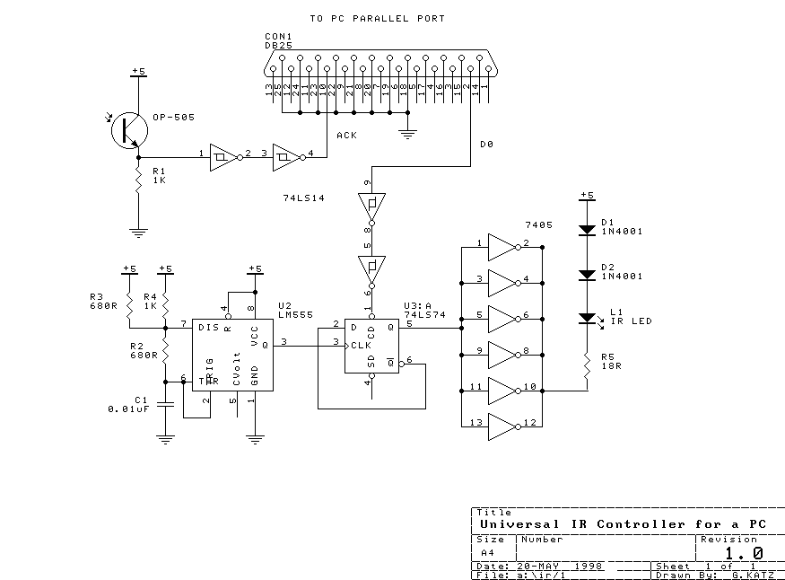
This circuit design comprises two main functional blocks: the IR receiver and the IR transmitter. The IR receiver utilizes an OP-505 IR phototransistor, which is sensitive to infrared light emitted by remote controls. The output from this phototransistor is initially weak and requires amplification and shaping, which is accomplished using a Schmitt trigger inverter (74HC14). The Schmitt trigger not only amplifies the signal but also provides a clean square wave output that is suitable for digital processing. This output is connected to the Acknowledge line of the parallel port (pin 10), allowing a connected PC to monitor and record the incoming IR signals.
The transmitter section begins with a 555 timer configured in astable mode, generating a clock signal at 80 kHz. This clock signal is fed into a 74LS74 D flip-flop, which divides the frequency by two, resulting in a 40 kHz square wave output. This frequency is typical for many IR remote controls and serves as the carrier frequency for the IR transmission. During playback, the software manipulates the D0 line of the parallel port to control the timing of the IR signal transmission, effectively recreating the recorded remote control signal.
The output from the D flip-flop is used to control the IR LED driver circuit. The driver section employs a 7405 hex open-collector buffer, which allows multiple outputs to be combined for increased current capability, ensuring that the IR LED can be driven adequately even when multiple LEDs are used. The inclusion of two 1N4001 diodes serves to regulate the voltage supply to the IR LED, stepping it down to approximately 3V, which is optimal for standard IR LEDs.
The circuit is designed to be flexible, allowing for adjustment of the 555 timer frequency to accommodate IR remote controls that operate at frequencies other than the standard 40 kHz. This adaptability makes the circuit versatile for a wide range of applications in home automation.
The accompanying software, available from GKDesign, enhances the functionality of the circuit, enabling users to record and playback IR signals, analyze waveforms, and create custom applications for controlling various devices. This opens up possibilities for automation and integration of home electronics, providing a user-friendly interface for managing IR-controlled appliances.This simple circuit allows you to record any IR remote control signal on your PC, and then play it back. This is particularly useful if you want to control appliances such as TVs, VCRs, CDs etc. from your computer. The device simply connects to the parallel port of your PC. You can also use this circuit to analyze the waveform from any IR remote control. The circuit consists of two parts. The first part is the IR receiver made up of a OP-505 IR photo transistor. This signal is buffered and squared up by the Schmitt trigger inverters (74HC14). The output of this inverter goes directly to the Acknowledge line (pin 10) of the parallel port. The software polls this line in the recording mode and stores the incoming data sequence. The transmitter consists of a clock generator (555) set to run at 80Khz followed by a 74LS74 D flip-flop. The flip-flop divides the clock signal by 2 giving a precise 50-50 duty cycle on a 40Khz signal. This is then used as a carrier for the transmitter section of the circuit. In playback mode the software turns the D0 line of the parallel port on and off at the same rate that it recorded the signal at.
This is used as a gate signal for the 40Khz carrier. The gate action is achieved by controlling the Clear input of the D flip-flop. If the clear line is low, then the Q output is also held low. This gated signal is then used to drive the IR LED via the driver section. The IR LED driver section consists of a 7405 hex open-collector buffer. All the outputs of the 7405 are tied together to give enough current to drive the IR LED. The two 1N4001 diodes are used to step down the voltage to around 3V for the IR LED. This may seem as an overkill but you can drive several IR LED's simultaneously. The 555 frequency can be adjusted for remote controls whose carrier frequency varies from the standard 40Khz. The record/playback software can be obtained free of charge from GKDesign. Please email us to get a copy of the executable and source code. The software allows you to record/playback and view any IR remote control signal. The real fun begins when you write your own software to control your house. For example, a program can be easily written that automatically programs the clock on your VCR, TV and anything else.
🔗 External reference
Related Circuits

The schematic for controlling the motors is divided into three main sections, each serving a distinct function. The primary components featured in the schematic include the PIC 18F252 microcontroller, the SN754410 motor driver, and 2N2222 transistors. At the top...
The SC41343 is designed as a type of infrared, ultrasonic, or RF remote control launch coding circuit. The internal circuit comprises a sequence generator, control logic circuit, 4-bit shift register, data extraction circuit, and latch circuit. Features include the...
When running large-scale software or games, a computer's internal temperature can increase significantly, especially during hot summer months. Although the machine is equipped with a CPU and graphics card fan, poor hot air circulation prevents immediate removal of heat...
The difference between these two ICs. A microcontroller is a specialized type of microprocessor designed to be self-sufficient and cost-effective, while a microprocessor is typically intended for general-purpose use, such as in personal computers (PCs). The microcontroller integrates several...
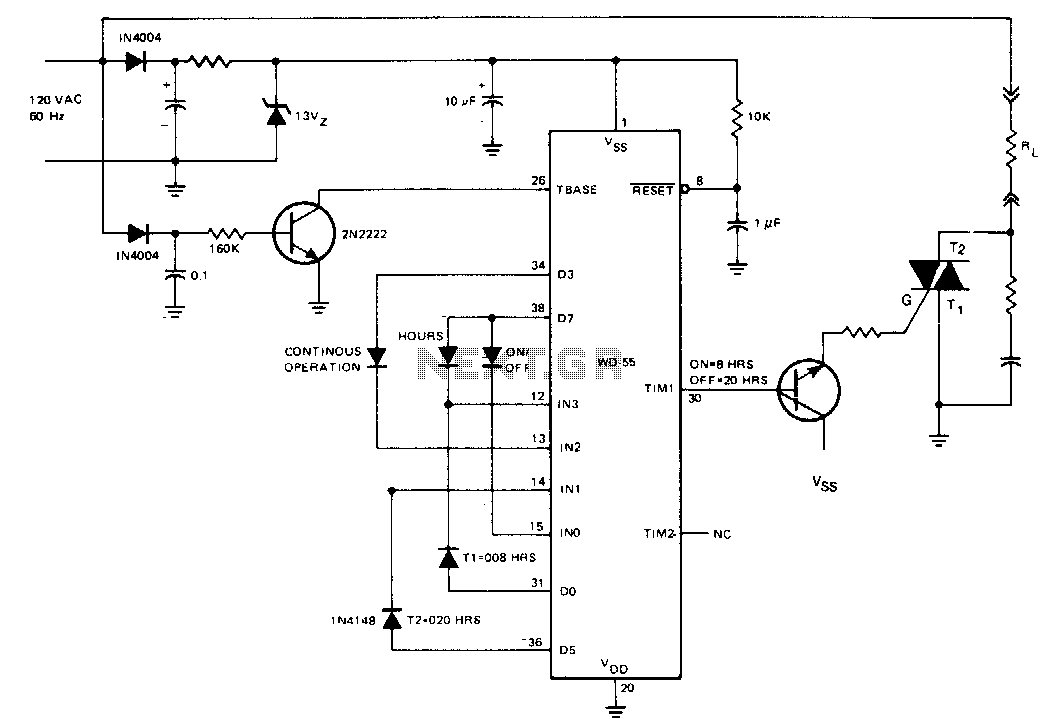
The AC line-operated on/off controller is a straightforward and dependable solid-state alternative to a motor-driven cam switch. Time intervals 1 and 2 are programmed using diodes to be 8 hours and 20 hours, respectively. The TIM1 output is buffered...
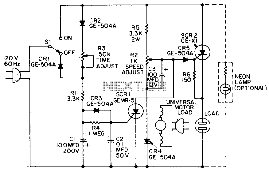
When the time delay expires, SCR1 conducts and removes the gate signal from SCR2, which stops the motor. Both the time delay and motor speed are adjustable by potentiometers R2 and R3. If heavier motor loads are anticipated, use...
Warning: include(partials/cookie-banner.php): Failed to open stream: Permission denied in /var/www/html/nextgr/view-circuit.php on line 713
Warning: include(): Failed opening 'partials/cookie-banner.php' for inclusion (include_path='.:/usr/share/php') in /var/www/html/nextgr/view-circuit.php on line 713