
IR Volume Remote
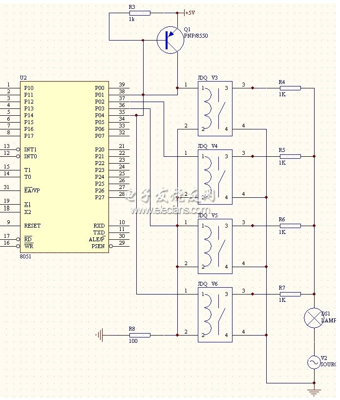
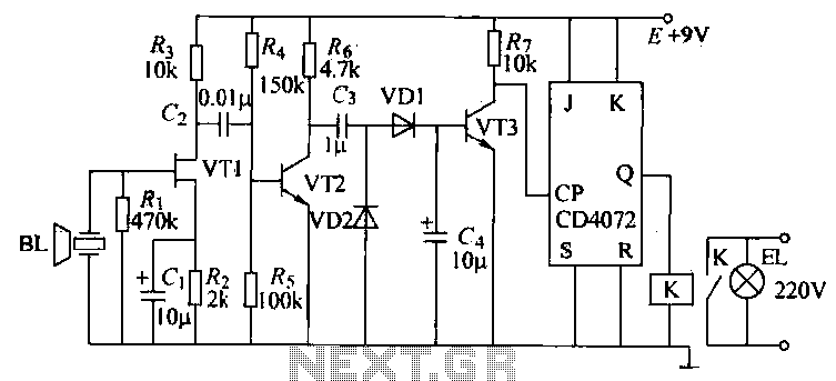
The remote controller circuit described functions as an interface for adjusting the volume of a preamplifier from a distance, utilizing infrared (IR) communication for signal transmission. The core of the circuit consists of a motor driver that is responsible for rotating the potentiometer, which in turn adjusts the volume level of the audio signal being processed by the preamplifier.
The IR component typically includes an IR receiver module that captures signals from a handheld remote control. The remote control sends specific commands, which are translated into electrical signals by the IR receiver. These signals are then processed by a microcontroller that interprets the commands to determine the required direction of rotation for the motor.
The motor driver circuit can be based on a H-bridge configuration, allowing the motor to rotate in both clockwise and counterclockwise directions. This capability is essential for adjusting the potentiometer to increase or decrease the volume. The motor is mechanically coupled to the potentiometer shaft, ensuring that the rotation of the motor directly translates to the movement of the potentiometer.
Power supply considerations for the circuit must include adequate voltage and current ratings to support both the IR receiver and the motor driver. Additionally, decoupling capacitors may be employed to filter out noise from the power supply lines, ensuring stable operation of the circuit components.
Overall, this remote controller design provides a convenient solution for volume control in audio applications, enhancing user experience by allowing adjustments from a distance without the need for physical interaction with the preamplifier.This remote controller can be fitted to any preamplifier for distance volume control. Basicly, Its a motor controller circuit with IR that turn the potentiometer left or right. 🔗 External reference
Related Circuits
A radio remote control system utilizing DTMF (Dual-Tone Multi-Frequency) technology is presented. This circuit allows for the control of various electrical appliances through radio frequency signals. The described radio remote control system employs DTMF tones, which are generated by a...
This system is a control system based on a single-chip computer that allows for remote operation of lighting. The scheme primarily addresses the transmission and reception of signals, as well as program manipulation of various signals once they are...
This circuit is designed to switch on or off any home or industrial appliance using a TV or DVD remote controller. The circuit can be operated up to a distance. The circuit utilizes an infrared (IR) receiver module, which detects...
The T-40-16 and 555 ultrasonic transmitter circuit configuration consists of an ultrasonic transmitter T-40-16 and a 555 timer circuit. By adjusting the potentiometer RP, the oscillation frequency of the circuit can be changed. The output pulse frequency from the...
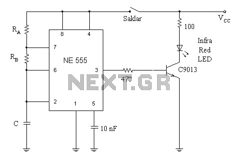
A simple circuit diagram illustrates a schematic for a remote control system, which consists of two components: a transmitter and a receiver. The transmitter circuit is controlled by the NE555 integrated circuit (IC). This system operates by detecting the...
Iron the printed layout at a low heat setting until the ink adheres to the PCB. This process may take over an hour to complete. Afterward, remove the transparent paper. Next, submerge the PCB in Ferric Chloride solution until...