
Isolated Telephone Interface
This circuit serves as a basic telephone interface that connects a standard telephone line to a tape recorder for recording phone conversations. It utilizes RJ-11 jacks, which are industry-standard connectors for telephone wiring. The circuit is designed to handle both the audio signal and the ringing voltage from the telephone line.
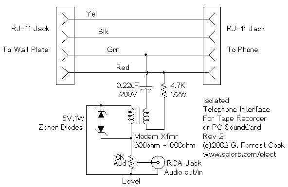
The red and green wires from the RJ-11 jacks carry the audio signal for a single phone line, while the yellow and black wires are typically reserved for a second line. The inclusion of a 0.22 microfarad capacitor is crucial as it blocks any DC component from the telephone line, ensuring that only the AC audio signals pass through to the transformer. This is important for protecting sensitive audio equipment, such as the tape recorder.
The transformer plays a vital role in this circuit, providing electrical isolation between the telephone line and the tape recorder. This isolation helps to prevent any potential damage to the recorder from high voltages present on the telephone line, particularly during ringing signals. The transformer also allows for impedance matching, which can improve the quality of the audio signal being recorded.
A 4.7K ohm resistor is incorporated into the circuit to limit the current of the 90V ringing signal. This is a protective measure to ensure that the high voltage does not exceed safe levels for the downstream components, particularly the tape recorder.
Zener diodes are used to clamp the ringing voltage and protect the tape recorder from transient voltage spikes. These diodes will conduct when the voltage exceeds a certain threshold, thereby shunting excess voltage away from sensitive components and preventing damage.
Finally, a 10K ohm potentiometer is included in the circuit to allow for level adjustment of the audio signal being fed into the tape recorder. This feature enables the user to optimize the recording level based on the specific requirements of the tape recorder and the volume of the incoming audio signal.
Overall, this circuit is a straightforward yet effective solution for interfacing a telephone line with a recording device, ensuring both functionality and protection for the equipment involved.There`s not much to this circuit. The two RJ-11 jacks are set up to feed the telephone circuit through from the wall to the phone. The active signal for a single phone is on the red and green wires. Yellow and black are usually used for a second phone line. The 0.22uF capacitor blocks any DC current from flowing through the transformer. The 4.7K resistor limits the current of the 90V ringing signal. The transformer isolates the telephone side of the circuit from the tape recorder side. The zener diodes clamp the 90 volt ringing signal and other transient spikes to protect your recorder. The 10K potentiometer is used to adjust the level to the tape recorder. 🔗 External reference
Related Circuits
A simple calculator, in conjunction with a chip-on-board (COB) from an analogue quartz clock, is utilized to create a telephone call meter. The calculator facilitates the conversion of STD/ISD calls into local call equivalents and consistently displays the current...
This is an improved version of the audio interface commonly used to connect a computer soundcard to a transceiver's receive and transmit audio circuits. This kind of interface is used by computer programs that send and receive SSTV, RTTY,...
A 50W isolated forward-converter switching supply for telecom applications is described. Most aspects of the design are discussed. The 50W isolated forward-converter switching supply is engineered to meet the specific demands of telecom applications, where reliability and efficiency are paramount....
This interface design has a long history. It is the first microcontroller design initiated in early 1998, which has evolved over the years. Initially, the schematic diagram for the first prototype was drafted in 1998, and it later became...
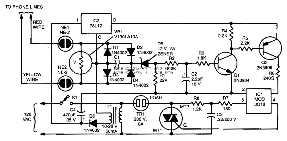
The two neon bulbs will illuminate when the voltage across the ringing circuit exceeds 100 V. These bulbs provide line isolation between the unit and the telephone line. Additionally, they function as a voltage divider for the bridge rectifier...
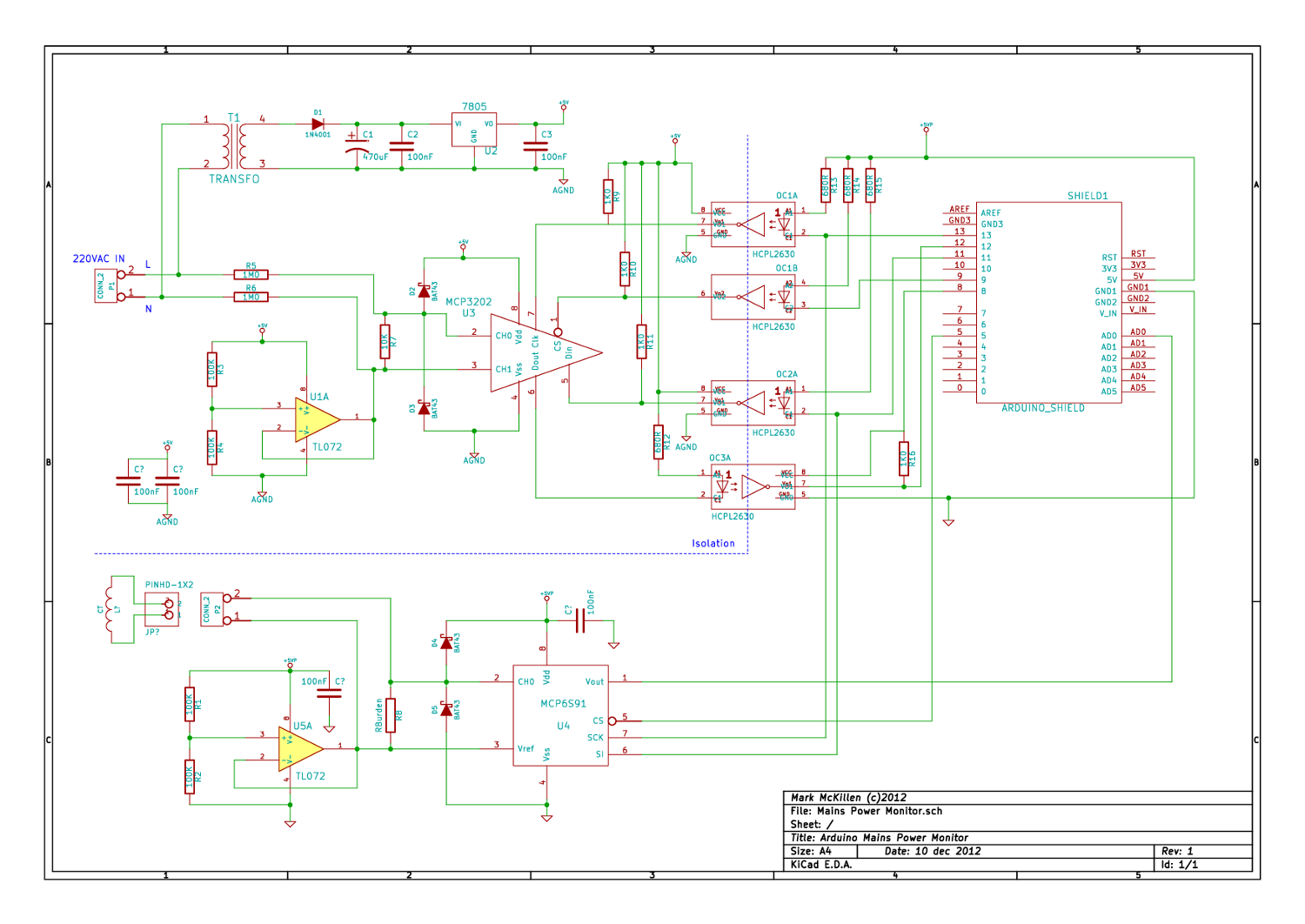
A mains (220-240VAC) power monitoring circuit has been sought for interfacing with an Arduino. While the OpenEnergyMonitor solution employs a transformer for isolation and measurement of mains voltage, it has been noted that the transformer does not couple effectively...