
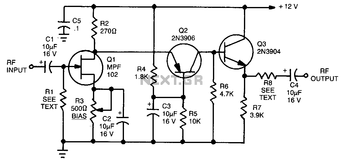
Jfet Wideband Amplifier
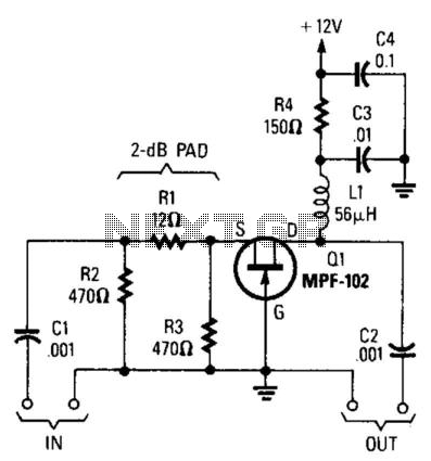
The circuit incorporates an MPF102 JFET, a commonly used device in RF applications due to its high input impedance and low noise characteristics. The input impedance of 50 ohms is suitable for matching with standard RF systems, ensuring minimal signal reflection and optimal power transfer. The load impedance of approximately 470 ohms indicates that the circuit is designed to interface with devices that require higher impedance levels, such as antennas or certain types of RF amplifiers.
To achieve effective impedance matching, a 3:1 transformer is recommended. This transformer will step down the load impedance from 470 ohms to 50 ohms, allowing the circuit to maintain proper operation without signal degradation. The transformer should be designed to operate efficiently at VHF frequencies, ensuring that it does not introduce significant losses or distortions to the signal.
The gain of the circuit, estimated between 6 to 8 dB at VHF frequencies, indicates that the circuit is capable of amplifying weak signals, making it suitable for applications such as signal reception in radio systems or as part of a larger RF front-end. The gain can be influenced by various factors, including the biasing of the JFET and the quality of the matching transformer. Proper design and component selection are crucial to achieving the desired performance characteristics and ensuring reliable operation within the intended frequency range.
In summary, this circuit design utilizing the MPF102 JFET is well-suited for applications requiring high input impedance, effective impedance matching, and reliable amplification at VHF frequencies, making it a valuable component in RF circuit design. Using an MPF102 JFET, this circuit has a 50- input impedance. Load impedance should be about 470 . A 3:1 matching t ransformer can be used to get the impedance back to 50 . This circuit will show about 6- to 8-dB gain at VHF frequencies. 🔗 External reference
Related Circuits
This tutorial provides information related to sensor amplifiers, schematics, and noise. It presents a discussion around sensors and their outputs. Sensor amplifiers are critical components in various electronic systems, especially in applications where signals from sensors need to be conditioned...
This is a four-channel amplifier designed for use with quadraphonic equipment, such as a Sound Blaster Live card. There is no volume control; audio levels are managed directly by the sound card. The construction is straightforward and suitable for...
The TDA2822 is a low-power stereo operational amplifier commonly utilized in Walkman devices and headphones. It is capable of delivering an output power of 250 milliwatts. This operational amplifier is particularly suitable for low-volume production applications and serves as...
The circuit features a frequency response ranging from 100 Hz to 3 MHz, with a gain of approximately 30 dB. Field-effect transistor Q1 is configured in a common-source self-biased mode. An optional resistor R1 allows for the adjustment of...
Dynamic microphones are versatile and ideal for general-purpose use. They utilize a straightforward design with minimal moving parts, making them relatively sturdy and resilient to rough handling. These microphones are better suited for high volume levels, such as those...
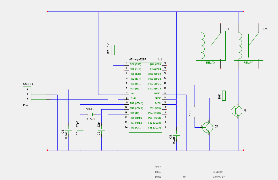
If a Squeezebox is present, it is likely accompanied by an amplifier. The inconvenience of manually turning the amplifier on and off, especially when the Squeezebox is stored in a cupboard, necessitates a device that automatically powers the amplifier...