
Jogging Timer
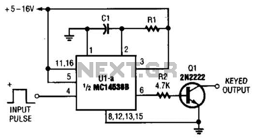
The described circuit functions as a timer with an adjustable duration for auditory feedback, specifically designed for jogging intervals. The heart of the circuit is a microcontroller or a timer IC that manages the timing intervals. The rotary switch, SW1, allows the user to select the desired time delay, which ranges from 1 to 9 minutes.
In each position of the rotary switch, a different resistor or capacitor configuration may be employed to set the timing interval. For instance, in position 1, the circuit might utilize a specific resistor-capacitor (RC) time constant that corresponds to a 1-minute delay. As the switch is rotated to subsequent positions, the time constants would be adjusted accordingly to produce delays of 2, 3, up to 9 minutes.
The Piezo sounder serves as the output device, providing audible cues to the user. The microcontroller or timer IC triggers the sounder to emit three short beeps at the end of each selected interval. This operation can be achieved using a simple transistor switch to drive the Piezo element, ensuring that sufficient current is supplied to produce a clear sound without damaging the microcontroller.
Power supply considerations for the circuit should ensure compatibility with the components used, typically requiring a low-voltage DC source. Proper decoupling capacitors should be included near the power pins of the microcontroller or timer IC to filter out any noise that may affect performance.
Overall, this circuit design combines user-friendly interface elements with effective timing and output capabilities, making it suitable for applications where interval timing and auditory feedback are essential, such as in fitness routines.This circuit was developed since a number of visitors of this website requested a timer capable of emitting a beep after one, two, three minutes and so on, for jogging purposes. As shown in the Circuit diagram, SW1 is a 1 pole 9 ways Rotary Switch. Setting the switch in position 1, the Piezo sounder emits three short beeps every minute. In position 2 the same thing happens after a 2 minutes delay, and so on, reaching a maximum interval of 9 minutes in position 9.
🔗 External reference
Related Circuits
With switch SI in the off position, battery voltage is applied across timing capacitor CI, which remains charged while the rest of the circuitry is powered off. Transistor Q1, and consequently transistors Q2 through Q4, remain in an off...
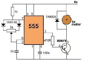
This project utilizes a 555 timer to control the speed of a 6-volt DC motor. Speed adjustment is achieved by rotating a 50 kΩ potentiometer either to the left or right. The circuit employs the 555 timer in astable mode,...
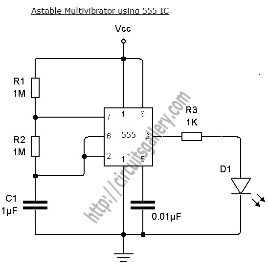
An astable multivibrator can be designed using a 555 timer IC, operational amplifiers, or transistors. The 555 timer IC provides accurate time delays ranging from milliseconds to hours, with the frequency of oscillation adjustable through simple modifications. This is...
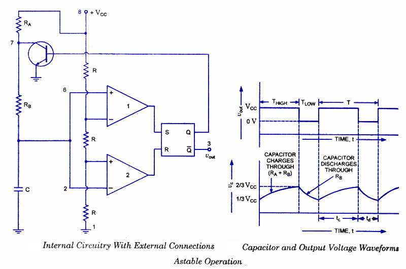
An astable multivibrator, often referred to as a free-running multivibrator, is a rectangular-wave generating circuit. Unlike the monostable multivibrator, this circuit does not require any external trigger to change the state of the output, hence the term free-running. Before...
This timer is intended for individuals seeking to achieve a tan while minimizing excessive exposure to sunlight. A rotary switch adjusts the timer based on six categorized photo-types. A photoresistor modifies the preset time value in relation to sunlight...
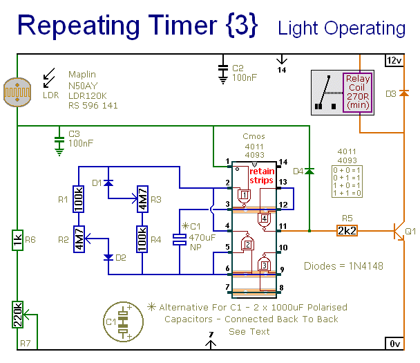
This circuit closely resembles Repeating Timer No. 2. However, the inclusion of a light-dependent resistor (LDR) allows the timer's operation to be confined to daylight hours. Resistor R7 enables the adjustment of the light level at which the timer...
Warning: include(partials/cookie-banner.php): Failed to open stream: Permission denied in /var/www/html/nextgr/view-circuit.php on line 713
Warning: include(): Failed opening 'partials/cookie-banner.php' for inclusion (include_path='.:/usr/share/php') in /var/www/html/nextgr/view-circuit.php on line 713