
Relay Coil Energy Saver
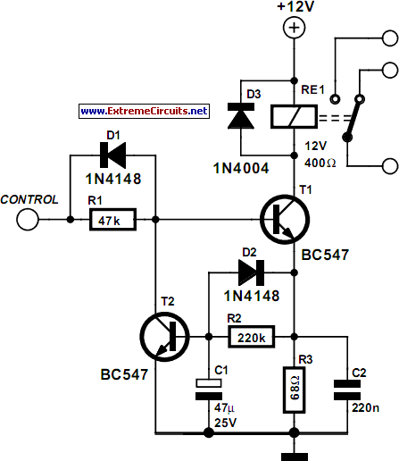
The described circuit employs a relay control mechanism that optimizes energy efficiency and minimizes thermal effects during prolonged operation. The relay coil is initially energized with full voltage to ensure reliable operation, facilitated by capacitor C2, which provides a brief surge of current. Once the relay is activated, the circuit transitions to a lower hold current mode, achieved through the configuration of resistors R2 and R3, and transistor T1, which regulates the current flowing through the relay coil.
The equations provided allow for precise calculations of component values, ensuring that the circuit is tailored to the specific characteristics of the relay being used. The use of capacitors C1 and C2 is critical in managing timing and current flow. C1 not only sets the delay for re-energizing the relay but also influences the hold current, while C2 provides the necessary initial surge for quick activation. The delay network formed by C1 and R2 is pivotal for controlling the transition between the pull-in and hold current states.
Diodes D1 and D2 play essential roles in maintaining circuit functionality. D1 ensures that C1 discharges rapidly, preventing any unintended relay activation during the off state, while D2 manages the discharge of C1 when the control signal is low, preserving the integrity of the relay's operation.
This circuit configuration is particularly beneficial in applications where relays are frequently cycled on and off, as it reduces energy consumption and prolongs the lifespan of the relay by mitigating heat buildup. The careful selection of component values based on the relay specifications is crucial for optimal performance, and experimentation is encouraged to refine the timing and current characteristics to meet specific operational requirements.Some relays will become warm if they remain energized for some time. The circuit shown here will actuate the relay as before but then reduce the hold` current through the relay coil current by about 50%, thus considerably reducing the amount of heat dissipation and wasted power. The circuit is only suitable for relays that remain on for long perio ds. The following equations will enable the circuit to be dimensioned for the relay on hand: R3 = 0. 7 / I Charge time = 0. 5 G— R2 G— C1 Where I is the relay coil current. After the relay has been switched off, a short delay should be allowed for the relay current to return to maximum so the relay can be energized again at full power. To make the delay as short as possible, keep C1 as small as possible. In practice, a minimum delay of about 5 seconds should be allowed but this is open to experimentation.
The action of C2 causes the full supply voltage to appear briefly across the relay coil, which helps to activate the relay as fast as possible. Via T2, a delay network consisting of C1 and R2 controls the relay coil current flowing through T1 and R3, effectively reducing it to half the pull in` current.
Diode D2 discharges C1 when the control voltage is Low. Around one second will be needed to completely discharge C1. T2 shunts the bias current of T1 when the delay has elapsed. Diode D1 helps to discharge C1 as quickly as possible. The relay shown in the circuit was specified at 12 V / 400 ohms. All component values for guidance only. 🔗 External reference
Related Circuits
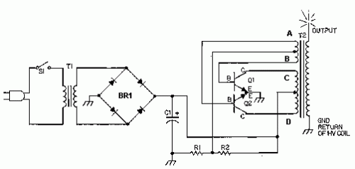
This circuit is designed to demonstrate high-frequency high voltage, capable of producing voltages up to approximately 30 kV, depending on the transformer used. It is economical and straightforward to construct, primarily utilizing a standard TV flyback transformer. The circuit...
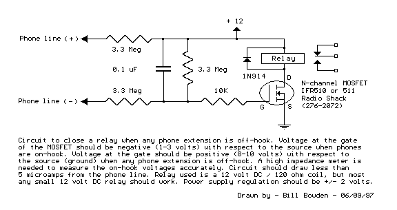
Circuit to close a relay when any phone extension is off-hook. Voltage at the gate of the MOSFET should be negative (1-3 volts) with respect to the source when phones are on-hook. Voltage at the gate should be positive...

This circuit was designed for use in a hi-fi showroom, where a choice of speakers could be connected to a stereo amplifier for comparative purposes. The circuit serves as a speaker selector that facilitates the connection of multiple speakers to...
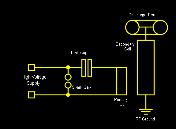
Due to the high voltages present in the Charge and Primary sections, it is logical to seek cables with high voltage ratings, such as neon sign cables, medical X-ray equipment cables, and car engine spark plug leads. The first...
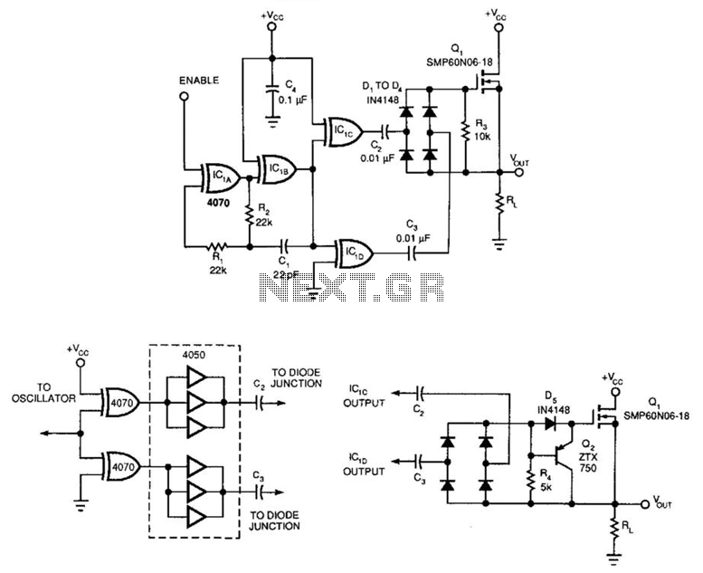
A power MOSFET paired with a quad exclusive-OR oscillator forms an efficient solid-state relay. The capacitively isolated drive circuit provides the necessary gate drive to activate the n-channel device. This setup includes a gated oscillator (IC1A and IC1B operating...
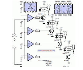
This circuit demonstrates that microprocessors, personal computers, and the latest ultra-accurate digital-to-analog converters (DACs) are excessive for the task of sequentially controlling four relays. The circuit utilizes a simple microcontroller or a basic timer IC to manage the operation of...
Warning: include(partials/cookie-banner.php): Failed to open stream: Permission denied in /var/www/html/nextgr/view-circuit.php on line 713
Warning: include(): Failed opening 'partials/cookie-banner.php' for inclusion (include_path='.:/usr/share/php') in /var/www/html/nextgr/view-circuit.php on line 713