
Automatic Audio Shutoff
This circuit operates by utilizing an audio signal to control the power supply to connected devices, effectively integrating audio detection with timing capabilities. The audio input is processed through an operational amplifier (IC1a) that amplifies and filters the signal, with a roll-off occurring at approximately 1.25 kHz at -6 dB per octave. The subsequent stage (IC1b) employs a two-pole filter with a cutoff frequency around 1 kHz and unity gain, resulting in a combined roll-off of 18 dB per octave. This filtering is crucial for eliminating noise and high-frequency interference, particularly in applications involving FM or TV audio sources.
The output from the filtering stages is converted to a DC level using diodes D1 and D2, with capacitor C6 providing charge storage. Resistor R10 discharges C6 when the audio signal is absent. The comparator (IC1c) is configured for rapid switching, utilizing positive feedback to ensure that when the rectified signal at the non-inverting input exceeds the threshold set by potentiometer R11, the output switches off quickly. When an audio signal is detected, LED1 illuminates, indicating active audio input, while the output of IC1c triggers an OR gate formed by IC1d, causing transistor Q4 to saturate. This action energizes the coil of reed relay Relay1, closing its contacts and allowing AC power to flow to the multiple outlets.
When the audio signal drops below the sensitivity threshold, IC1c rapidly switches off, initiating a timer in IC2. The output from this timer (pin 5) maintains the OR gate's operation until the timer expires, keeping power supplied to the AC outlets. If an audio signal reappears within the timeout interval, a brief pulse from IC2 resets the timing capacitor, ensuring that the most recent audio signal dictates the timing delay.
Transistors Q1 and Q2 serve as a quenching mechanism, grounding the comparator signal just before shutdown to prevent any audio "thump" from retriggering the timer. The use of a reed relay provides electrical isolation between the control circuit and the triac, which should be adequately heat-sinked to handle the load.
The timer function is selectable via switch S3, which toggles between normal and timer modes, adjusting the timing capacitor's configuration. Potentiometer R17 allows for fine-tuning the timer delay, with different maximum durations depending on the selected mode. To operate the unit, S3 should be set to normal, both potentiometers adjusted to mid-position, and the reset button S1 pressed. In this state, LED1 should illuminate, indicating that devices connected to the AC outlets are powered. If the audio signal is absent, the LED will turn off, and the connected devices will shut down after the timer expires, with a maximum duration of approximately 20 minutes in normal mode and 2 hours in timer mode.The purpose of this circuit is to automatically turn off any device plugged into its power outlets after a certain period of time. Shutoff is activated by an absences of an audio signal or by a standard timer function. This unit would be connected to speaker terminals of a stereo system, tape outputs, TV earphone jack or audio outputs etc.
Once the audio signal drops below a predetermined level a timer function will turn off any device powered by the outlets on the back of this unit. For example, if you like to fall asleep listening to your CD player. This unit could be hooked up to your speaker terminals. After the CD is done playing the audio signal would drop below the threshold value and the unit would turn off your stereo system after a certain timer interval had passed and therefore you would not have to worry about falling asleep and having your stereo being on all night.
This controller can also be used as a standard timer control without the audio input and turn devices off after a preset time interval. The outlets can handle loads of up to 1200 watts and the unit is fused with a 10 amp fuse for protection.
This is how the unit works. The audio signal goes into IC1a for amplification and filtering with a roll off occurring about 1.25khz at -6db per octave. The second stage, IC1b is a 2 pole filter with a cutoff frequency is approximately 1 khz with unity gain.
The 2 stages have a combined roll off of 18db per octave to remove any noise and filter out any high frequency hiss if a radio station of TV station goes off the air. This is helpful if the audio source is either FM or TV. The filtered DC level of D1, D2 and C6 with R10 "bleeding" the charge from the capacitor C6 when the signal is not present.
IC1c is used as a comparator having fast "snap action" (positive feedback) so that when the rectified signal applied to the non-inverting (+) input exceeds the level set by the sensitivity control R11, the output switches off very rapidly. When IC1c output is high (audio signal is present), LED1 is turned on and current limited by R15. IC1c output signal turns on the OR gate formed by IC1d which in turn, causes Q4 to saturate and draw current through the coil of reed relay, Relay1.
With the reed relay contacts closed, gate power is applied to the triac, and power is present across the multiple AC outlets. This turns on any device connected to these sockets. When the audio signal either disappears or falls below the pre-set sensitivity threshold, comparator IC1c switches off rapidly.
This action also starts one of the timers in IC2 whose output pin (pin5) keeps the OR gate operating until the timer times out. Power remains on the AC outlets. If another audio signal should appear within the time-out interval, the second timer within IC2 will generate a 5 millisecond pulse which will turn on Q3 and discharge the main timing capacitor.
This resets IC2 back to zero and ensures that the last audio signal is always the one that begins the time out delay. Transistors Q1 and Q2 act as a "quench" circuit by grounding the comparator signal an instant before shutdown.
This is necessary because some audio power amplifiers generate a "thump" when turned off and this may retrigger the timer and never allow the system to shutdown. Reed relay Relay1 is necessary for complete isolation between the circuit and the triac. The triac should be heat sinked. The timer function is determined by the setting of normal/timer switch S3, which disables the input circuit by turning on the "quench" transistor, Q1 and connecting the a larger capacitor in parallel with the main timing capacitor.
Potentiometer R17 sets the timer delay in either case, although the range for normal and timer positions of S3 is different. To operate the unit set S3 in the normal position and both pots in the mid position and then press the rest button S1.
LED1 should turn on ad any device plugged into the AC outlets should turn on. With no audio signal present the LED will go out and the unit will turn off any devices plugged into after the timer expires. The time length is set by R17. Connect an audio source to the unit and adjust the sensitivity control R11 until the LED remains on continuously.
The time delay for normal is maxed out at around 20 minutes and in the timer mode it is maxed out at 2 hours. 🔗 External reference
Related Circuits
Most blog posts involve short 3-4 hour projects or hacks that are built for learning and enjoyment. It was time to develop something more substantial. The project described appears to focus on creating electronic circuits that can be completed within...
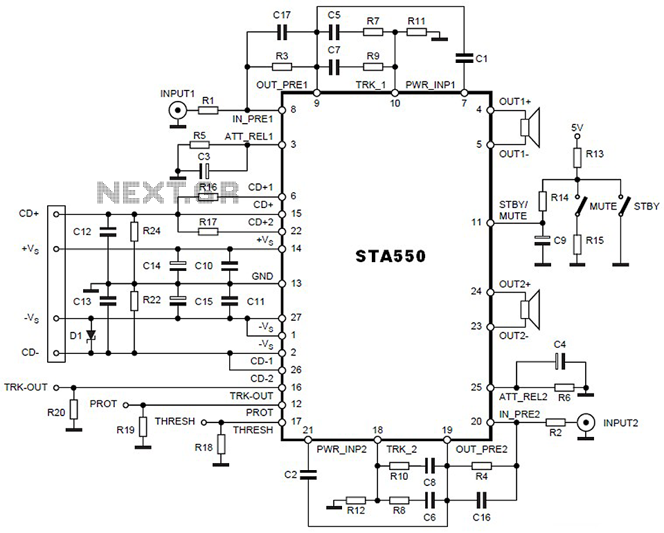
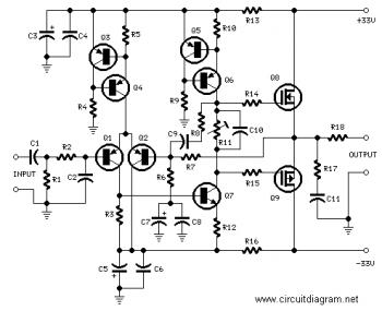
This is a 2 x 70W audio power amplifier circuit built using a single IC STA550. The amplifier circuit requires a few external components, primarily resistors and capacitors, and is straightforward to design. The STA550 audio amplifier can provide...
The Audionics CC-2 is named after Cliff Moulton, the chief engineer, and Charles Wood, the president of Audionics. However, the true designer of the amplifier is Bob Sickler, whose initials, "RLS," appear on the schematics. Following Bob's passing in...
This circuit can be directly connected to CD players, tuners, and tape recorders. It requires the addition of a 10K logarithmic potentiometer (dual gang for stereo) and a switch to accommodate various sources. Proper grounding is crucial to eliminate...
This circuit utilizes two quad op-amps to create an eight LED audio level meter. The op-amp employed in this circuit is the LM324, a widely used integrated circuit that is readily available from numerous electronic component suppliers. The 1K...
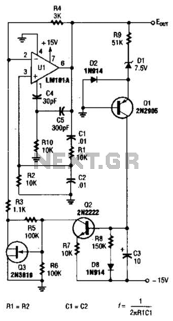
For variable-frequency operation, Rl and R2 can be replaced by a dual potentiometer. In electronic circuits that require variable-frequency operation, the use of a dual potentiometer as a replacement for resistors Rl and R2 can provide enhanced functionality and flexibility....