
Keypad Combination Lock Relay
The electronic combination lock described operates on a straightforward yet effective principle for securing access to various devices and areas. The system is built around a microcontroller known as the Nutchip, which interprets input signals from a keypad and controls a relay to engage or disengage the locking mechanism.
The keypad consists of ten buttons, numbered 0 through 9, with only four designated buttons—specifically 6, 7, 8, and 9—used to form the unlock sequence. These buttons are connected directly to the microcontroller’s input pins (IN1 to IN4). The design ensures that only the correct sequence will unlock the system; any incorrect input will trigger a reset of the microcontroller to its initial state, effectively locking the device again. This is accomplished by the additional keys being wired in parallel to the ST0 input pin, which serves as a reset trigger.
The Nutchip processes the inputs based on a truth table that defines valid versus invalid sequences. When a valid sequence is entered, the microcontroller activates a relay, which can control a locking mechanism or power to a specific device, thereby allowing access. The relay acts as an electronic switch, enabling or disabling the flow of electricity to the locked device.
The versatility of this electronic lock system allows it to be employed in various applications beyond traditional locks. It can be used for securing electronic devices, making it suitable for environments such as offices, schools, and public facilities where access control is necessary. Furthermore, the potential for integrating a remote control feature enhances user convenience, allowing for wireless operation of the locking mechanism.
Overall, this electronic combination lock provides a modern solution to access control, combining security with ease of use, and is adaptable for multiple scenarios where traditional locking mechanisms may fall short.Only one out of 9,999 possible codes has the power to unlock this simple, yet effective, electronic lock. A combination lock is not just a perfect system to protect your belongings, it is also a valid system to let everyone to know that you are vigilant: an electronic system with a silicon heart is controlling the area, day and night without interruption, so everyone is warned!
You can use this combination lock circuit as a replacement or in addition to normal locks. It is very handy when a group is entitled to enter a common area, as parking lots or sport resort facilities for example. It is often the case where traditional keys are expensive, not appropriate or just not convenient: not to mention when the keys need to be replaced very often (e.g.
in the case of parking lots the cars can change). Compare the convenience of distributing a new access code to the requirement of making a new run of keys... This electronic lock is excellent also for locking devices powered by the electricity. A phone line, a photocopier, children's TV, a fax or a water pump: these are just a little selection of devices that can be locked with a combination lock.
And did we mention the option for adding a remote control? The basic blocks of this electronic combination lock are the keyboard, the Nutchip and the relay. The keyboard counts 10 keys, labelled with numbers 0 to 9. Four keys (actually simple normalli-open pushbuttons) connect directly to Nutchip inputs IN1...IN4. If you follow precisely the schematic we give, you get the combination 6-7-8-9. Any other key sequence will lock the device until the correct sequence is entered again. The correct sequence is determined by the truth table. In order to detect wheter a wrong key has been touched or not, the remaining keys (those not included in the combination) are connected in parallel and drive input ST0. This special pin causes the Nutchip to reset and restart it from state zero (st00), regardless of current state and other pin's situation.
Therefore, touching the wrong key will cause the Nutchip to restart from state zero. 🔗 External reference
Related Circuits
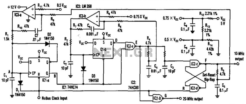
This circuit generates a 20-MHz clock signal that is phase locked to a 10-MHz clock found in the Apple MAC II. To create the 20-MHz output, the circuit generates a 25 ns negative-going pulse that is delayed by 50...
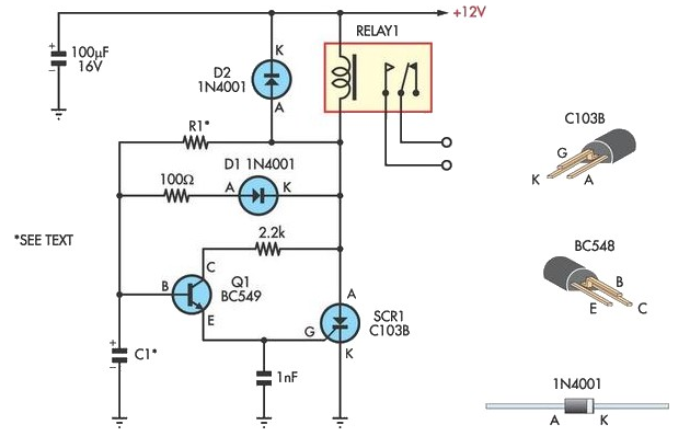
This circuit is designed to provide delayed relay switching action at power on. The delay is a function of the time constant produced by the combination of components. The circuit operates by utilizing a timing element, typically a resistor-capacitor (RC)...

For those unfamiliar with electronics, it is important to understand that an oscilloscope essentially has a single timebase that moves the spot horizontally from left to right with consistent intensity. The vertical deviation corresponds to the input voltage. It...
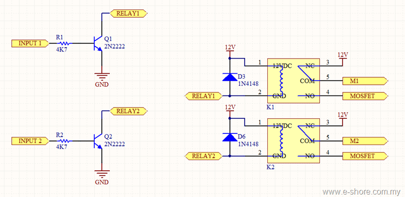
The circuit utilizes two sets of relays for each motor to switch the motor's direction, and one set of MOSFETs for each motor to control the motor's speed. The MOSFET and relay circuit will be divided into three parts...
Quartz clocks, which have dominated timekeeping for the past 20 years, have one issue: their errors, although slight, are cumulative. Quartz clocks operate based on the piezoelectric effect of quartz crystals, which oscillate at a precise frequency when subjected to...
The following circuit illustrates the iButton Electronic Lock Schematic diagram. This circuit is based on the Atmel AT89C2051 integrated circuit (IC). Features include an onboard power supply comprising a transformer (T1) and a voltage regulator (U4), a bridge rectifier...
Warning: include(partials/cookie-banner.php): Failed to open stream: Permission denied in /var/www/html/nextgr/view-circuit.php on line 713
Warning: include(): Failed opening 'partials/cookie-banner.php' for inclusion (include_path='.:/usr/share/php') in /var/www/html/nextgr/view-circuit.php on line 713