
pic based oscilloscope clock

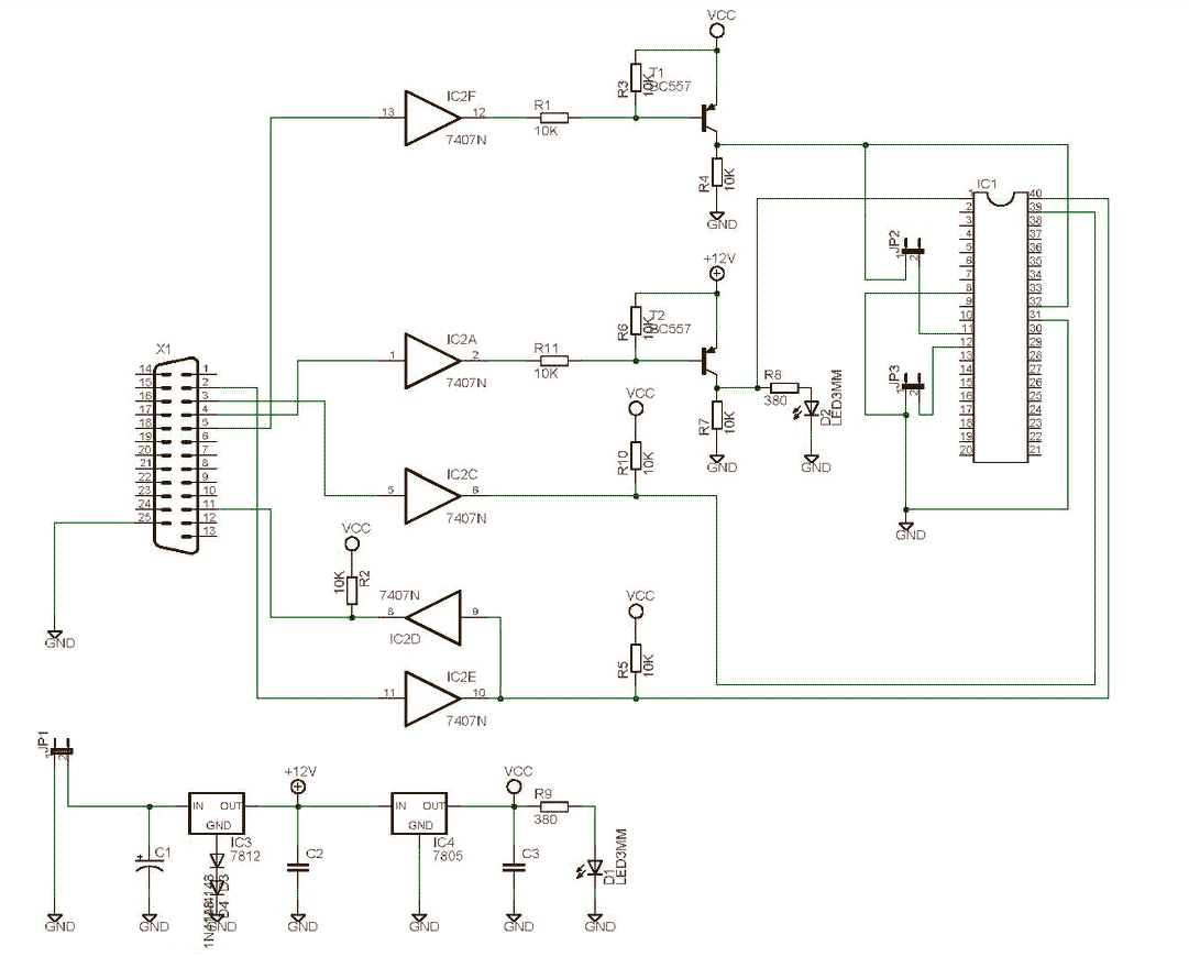
The described circuit utilizes an oscilloscope in X/Y mode to visually represent 7-segment digits. The oscilloscope's horizontal movement is controlled by a timebase, while vertical movements correspond to input voltage levels. A digital-to-analog converter (DAC) is essential for converting the digital signals from the PIC microcontrollers into analog voltages for both axes. The R2R ladder configuration is a common choice for creating a DAC due to its simplicity and effectiveness in achieving the desired voltage levels.
In this setup, two PIC microcontrollers are employed to generate the control signals necessary for the DAC. Each microcontroller can output digital signals that, when processed through the R2R ladder, yield the required voltage levels for the vertical segments of the 7-segment display. The additional voltage level serves as a reference point to position the oscilloscope spot when it is not actively drawing a segment.
To effectively display the digits, the circuit must account for the limitations of the oscilloscope. With the ability to only draw one vertical segment at a time, the system must cycle through the segments rapidly enough to exploit the human eye's persistence of vision. This technique allows for the perception of multiple segments being lit simultaneously, as the digits are displayed in quick succession—three periods per digit to ensure all segments appear illuminated.
The design requires careful timing and synchronization between the PIC outputs and the oscilloscope's sweep rate to ensure a coherent representation of the 7-segment digits. This approach allows for the effective use of an oscilloscope as a display device for digital representations, showcasing the versatility of electronic components and their applications in innovative ways.For those are not into electronics, you must know that an oscilloscope has basically only one timebase to move the spot horizontally from left to right with the same intensity. The vertical deviation is function to the input voltage. You understand immediately that you can`t directly display 7 segment digits, because you can`t move the spot from r
ight to left. By using X/Y mode, where the spot is controlled on two axes by two different voltages, it is possible to draw a picture (as in the examples mentioned above), but a fast digital to analog converter with two channels and at least 8 bits of resolution would be needed. By using 2 PIC outputs and a basic R2R digital to analog converter, we can have up to four different voltage levels : 3 for the vertical segment, and another one where to put the spot when it is not in use to draw a segment.
But the problem is that a 7 segment digit may have up to 3 horizontal lines at a time (like 2, 3, 8, 9. ) but we can draw only one during one spot deviation. So we will have to cheat with retinal persistence and use multiple frames : since we can have only one vertical segment per period, three periods will be needed to draw a full 7 segment digit.
🔗 External reference
Related Circuits
The SCHAER+ programmer is a programmer for PIC18 family from a PC parallel port (LPT). It is derived from the SCHAER programmer I used to download my projects in PIC1684. The SCHAER+ programmer should be improved to use a...
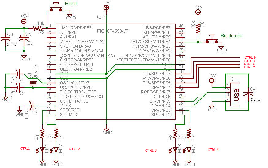
This project demonstrates a computer control interface using a USB board (USB Interface Project). This tutorial provides a straightforward method to control devices such as LEDs, motors, and other components via a computer using a USB board. Traditionally, devices...
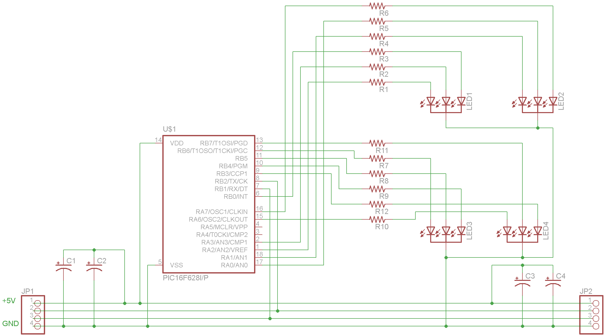
The complete schematic for the driver is provided. A PIC16F628 microcontroller has been selected due to its low cost, internal oscillator (4 MHz), and built-in USART. It is important to note that there is an error in the schematic;...
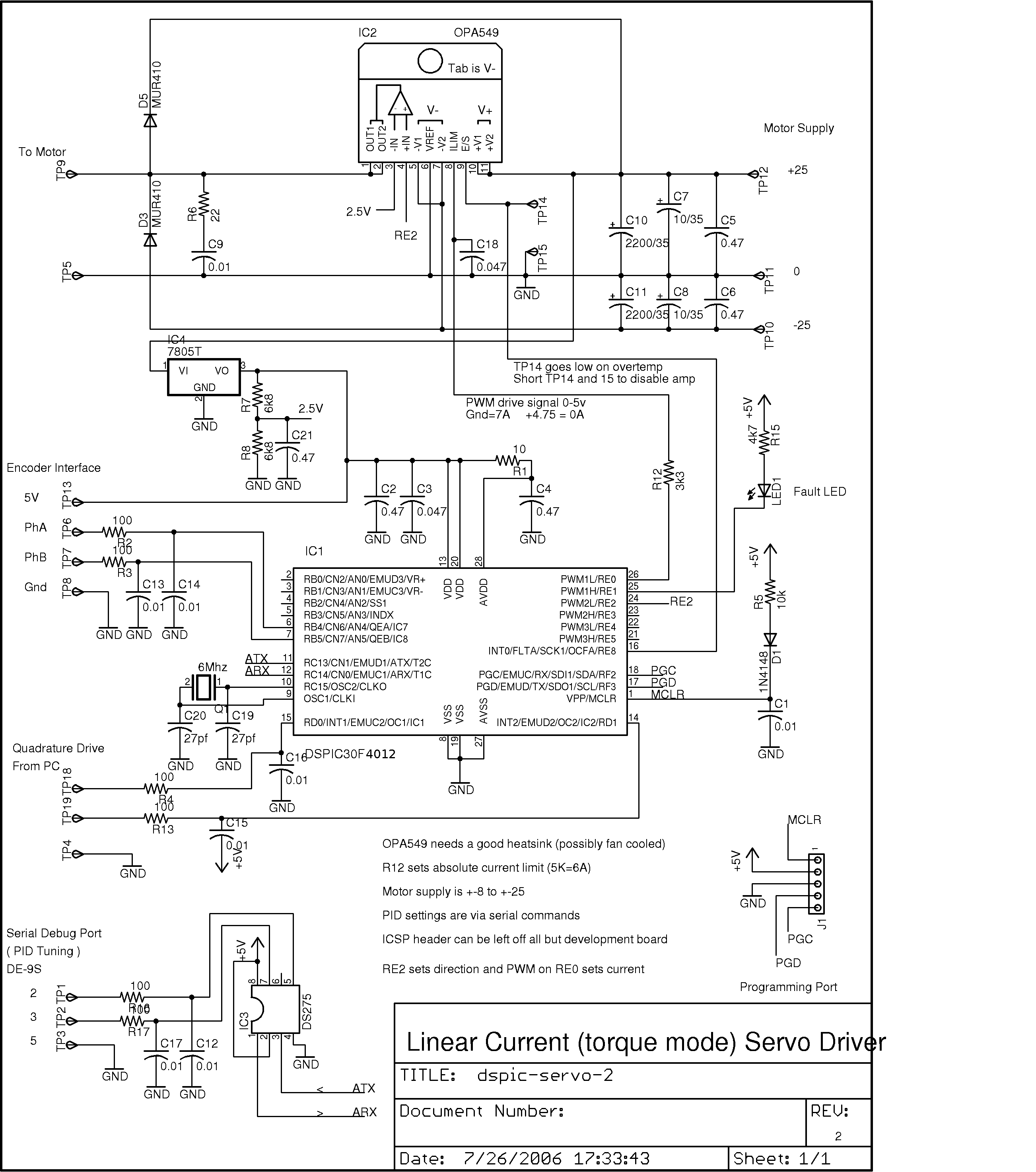
This project was developed as a cost-effective solution for driving small DC brushed motors as positioning servos for a desktop-sized CNC machine. The board interfaces with the PC through two pins of a parallel port, utilizing a quadrature drive...
This article describes a 2-Digit Counter using a Microchip PIC12F629. It shows what can be done with an 8-pin chip having just 5 output lines and one input line. The chip drives two 7-segment displays and this would normally...
One of the main considerations in phono preamplifier design is the choice between active (feedback) and passive equalization. An ideal feedforward preamplifier for a moving magnet cartridge would provide approximately 40 dB of gain before the equalizer (more for...