
Keypad-Operated Switch No.2

The Universal Keypad-Operated Switch circuit is designed to provide a user-friendly interface for controlling devices via a keypad input. The circuit operates on a voltage range of 5 to 15 volts, allowing for flexibility in power supply selection. The choice of relay is critical, as it must match the supply voltage, and if higher power devices need to be controlled, a multi-pole relay can be integrated for enhanced functionality.
The circuit’s operation begins with the relay being energized at power-up. The user must input a specific sequence of four keys connected to terminals A, B, C, and D to de-energize the relay. The common terminal is connected to R1, while all other keys are routed to terminal E. Pressing any of the keys connected to E will re-energize the relay, providing a straightforward method for resetting the circuit state.
For applications requiring reversed operation, substituting Q2 with a BC547 NPN transistor alters the default state of the relay to de-energized upon power-up. This modification allows the circuit to function in a manner where the user must enter the code to activate the relay, enhancing its utility in various scenarios.
Incorporating a keypad with a common terminal and individual connections for each key is essential for the circuit's operation. A standard 12-key keypad should provide 13 terminals, ensuring compatibility with the circuit design. The inclusion of eight "wrong" keys connected to E serves as a deterrent against unauthorized access, and utilizing a larger keypad with additional "wrong" keys can further enhance security measures.
Overall, the Universal Keypad-Operated Switch circuit is a versatile solution for controlling electronic devices, with a focus on simplicity and functionality while maintaining a level of security appropriate for many applications. Supporting documentation, including construction guides and parts lists, facilitates the assembly and implementation of this circuit in practical applications.This is a simplified version of the Universal Keypad-Operated Switch. I have modified the design to reduce the complexity of the circuit - and the number of components required. As a result - the code is somewhat less secure. However, there should be lots of situations where it will still be adequate. The circuit is drawn with a 12-volt supply - b ut it will work at anything from 5 to 15-volts. All you have to do is choose a relay suitable for the supply voltage you want to use. Replace the SPCO/SPDT relay with a multi-pole relay - if it suits your application. Do not use the "on-board" relay to switch mains voltage. The board`s layout does not offer sufficient isolation between the relay contacts and the low-voltage components. If you want to switch mains voltage - mount a suitably rated relay somewhere safe - Away From The Board.
Choose the four keys you want to use as your Code - and connect them to "A B C & D". Wire the common to R1 and all the remaining keys to "E". The circuit will power-up with the relay energized. To de-energize it - you must enter your code. To re-energize it - press any of the keys connected to "E". To reverse the operation of the circuit replace Q2 with a BC547. With an NPN transistor in this position - the circuit will power-up with the relay de-energized. To energize it - you must enter your code. To de-energize it again - press any of the keys connected to "E". Any keys not wired to "A B C & D" are connected to the base of Q1. Whenever one of these "Wrong" keys is pressed - Q1 takes pin 1 low and the code entry sequence fails. If you make a mistake while entering the code - simply start again. The Keypad must be the kind with a common terminal and a separate connection for each key. On a 12-key pad, look for 13 terminals. The matrix type with 7 or 8 terminals will NOT do. A 12-key pad has eight "Wrong" keys connected to "E". If you need a more secure code - use a bigger keypad with more "Wrong" keys. The Support Material for this circuit includes a step-by-step guide to the construction of the circuit board, a parts list, a detailed circuit description and more.
🔗 External reference
Related Circuits
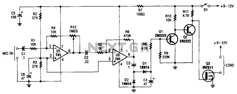
The audio-controlled switch utilizes a pair of 741 operational amplifiers, two 2N2222 general-purpose transistors, a hexFET, and several supporting components to create a circuit capable of activating devices such as a tape recorder, a transmitter, or virtually any other...
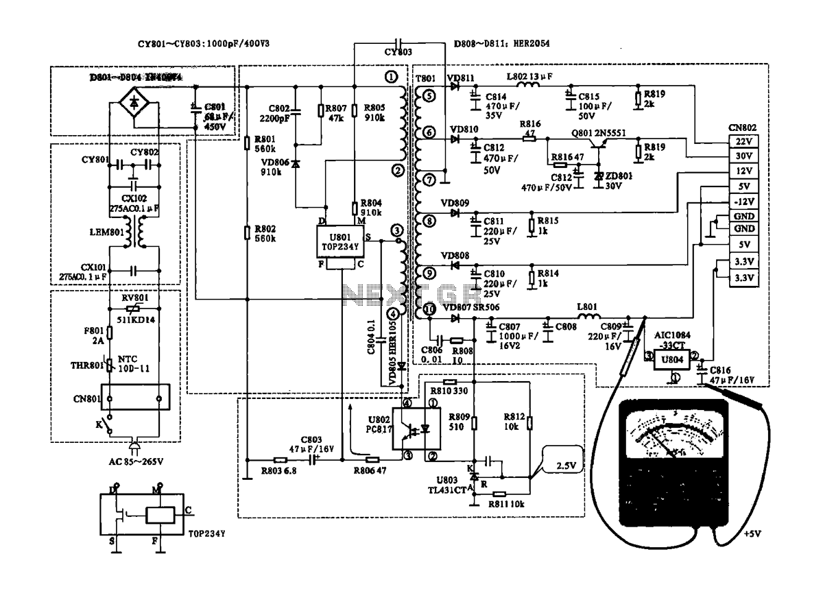
The Coship CDVB3188V receiver features a switching power supply circuit similar to the CDVB3188C model. The circuit includes several key components: an AC input circuit, an anti-jamming filter circuit, a complete flow filter circuit, and a switching oscillation circuit....
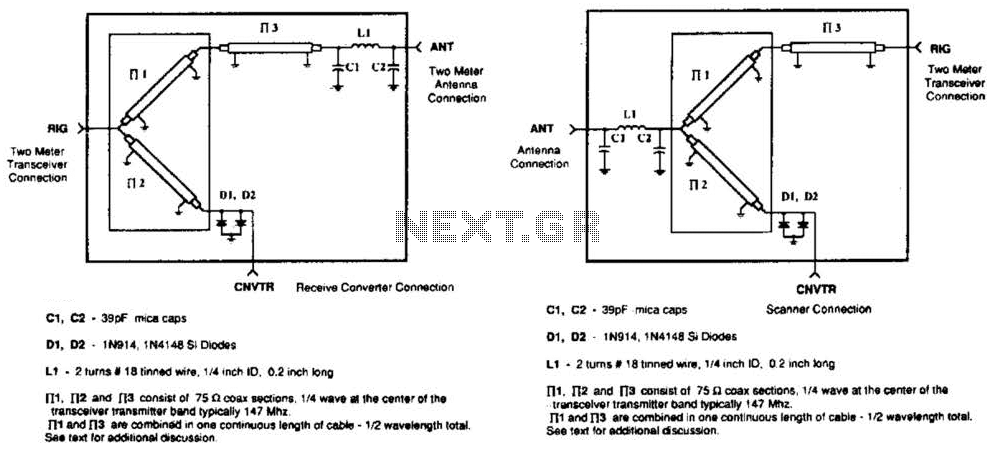
A pair of diodes and a quarter-wave transmission line are utilized as an automatic TR switch. D1 and D2 conduct during transmit periods, short-circuiting the scanner input. In this mode, the quarter-wave line appears as an open circuit. In...
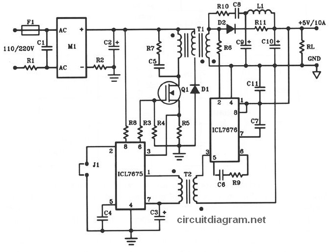
The following diagram illustrates the design of a 50W offline switching power supply circuit. This circuit is powered by a MOSFET, specifically the BUZ80A/IXTP4N8 for 220V AC input and the GE IRF823 for 110V AC input voltage. The output...
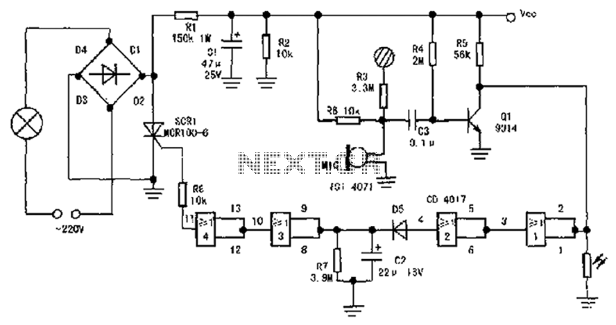
The circuit diagram illustrates a sound, light, and touch-controlled delay self-extinguishing switch. It comprises three main sections: the power circuit, the signal conversion detecting circuit, a delay circuit, and a control circuit. 1. Power Circuit: This section consists of...

This is a simple toggle switch that can be operated through sound signals such as a whistle or clap. The output of the toggle remains either low or high until... This circuit utilizes a sound sensor to detect specific audio...