
KG6MVBs Rig to Computer interface
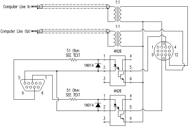
The modification described integrates a radio transceiver with a computer while ensuring electrical isolation to prevent interference from ground loops. The connection utilizes a 13-pin DIN connector, which is crucial for compatibility with various Icom radios. The audio coupling is achieved through 1:1 transformers, which maintain the necessary line level for both the radio and the computer's sound card. This design avoids the pitfalls of ground loops by not connecting the grounds of the two devices.
The transmit/receive control is managed through the RTS line, which is an efficient means of toggling the transmission state. The opto isolator plays a critical role in maintaining electrical isolation, preventing any potential noise or interference from the computer affecting the radio's performance. The use of an LED and phototransistor ensures that the only connection between the two systems is through light, thereby providing a robust isolation mechanism.
For the LED, a dropping resistor is essential to ensure that the voltage does not exceed the breakdown limit. The adjustment of the resistor value from the initial design reflects the common voltage levels found in laptop systems, illustrating the importance of understanding the specific voltage outputs of the devices involved. This careful consideration of component values and the design approach highlights the importance of thorough testing and adaptation in electronic modifications.
Overall, this modification showcases a practical application of electronic principles to enhance the functionality of radio equipment while minimizing the risk of interference, making it a valuable project for enthusiasts looking to connect their radios with computers effectively.This page describes a modification that you plug in to your radio and computer. Do this at your own risk! It`s your choice to do this. I`m not forcing it on you. If you don`t, hey, no hard feelings, but if you do and mess something up, don`t blame me. This was designed and tested on an Icom 718 HF rig and a Dell laptop. This should work on any Ico m rig that has a 13 pin accessory port, however I have only tested it on my 718. Kenwood rigs have a similar port, however the pin outs are different so beware! I am the type of person who likes to push every button, twist every knob, and try every option on any piece of electronics I get my hands on. After purchasing my Icom IC-718, I discovered the page in the manual where that mysterious 13 pin accessory connector on the rear was documented.
Since I know that I can not be cured, I had to put it to use. As a bonus, If I can build it myself - need I say more The main purpose of this device is to provide total isolation between the computer and the rig. You don`t want to create ground loops connecting it all directly. Computer hash in your HF rig will make you miserable, and RF in the computer. isn`t Windows unstable enough Many of the parts I used were from my junk box. For the parts I did not have, I found them at All Electronics, which is a electronics surplus store about 10 miles from work.
I do NOT recommend Radio Shack for parts, as they are very overpriced, if they even have the part! If you do not have an electronics store in your neck of the woods, I would suggest looking online. The only part I had trouble finding was the 13 pin DIN connector. I found one at HRO - it is for a Kenwood, but they are universal. The audio is coupled through 1:1 transformers. These are the type you find in modems. You do not want to use step-up or step-down, as they will change the levels. I was happy to discover during testing that both the modulator input and the output on the 13 pin connector are at line level. Computer sound cards are also at line level, so this part is super simple. I was able to use the sound control panel within Windows for all my audio adjustment. Since I didn`t want any possibility of ground loops, I did not connect the grounds together. In the pictures you will notice that I have one plastic plug, and one metal one. This is only so I can tell which one is which. The cable I used was an old shielded patch cable, which I cut the RCA ends off. Every piece of software I looked at uses the left channel (tip), so connect there. This completes the audio portion of the circuit. Next, you need to control transmit / receive. Most software will toggle either the RTS or the DTR line. I chose RTS (pin 7). What this means, is when the software wants to transmit, that pin goes high (positive voltage). In receive, it returns to zero. On my ham rig, the ptt circuit floats high, and when you pull it down, you transmit. This circuit could have been done several ways. one way is with a transistor as a switch. Unfortunately, this does NOT provide total electrical isolation. The second way would be a relay. The third, is an opto isolator. Inside the opto isolator, there is an LED and a phototransistor. When you light up the LED, the transistor conducts. Since the only connection is light, you maintain your isolation. This LED only requires 1. 18 volts (1. 5 max) with a current draw of 100mA. Breakdown voltage is only 6 volts, so we better put a dropping resistor in there! I put the reverse bias diode, so if we have reverse voltage, it has somewhere to go, and doesn`t build up to the breakdown voltage.
On my initial design, I assumed we were dealing with 12 volts. I put in a 1. 2k resistor, and nothing happened. Troubleshooting showed me that my laptop was only putting out 5 volts. I turns out this is typical. Most desktop systems use a 12 volt standard, and laptops 5 volts. I changed the resistor to 51 ohms, and it works well no 🔗 External reference
Related Circuits
An essential component of modern multimedia computers is the presence of two active audio speakers, which are typically mounted on or placed next to the monitor. Due to various physical limitations, these small computer speakers are unable to reproduce...

This application note discusses the use of SEPIC power modules to supply the necessary power for driving high-brightness LED arrays. These arrays serve as display backlights and necessitate a wide dimming range. The SEPIC configuration offers an efficient and...
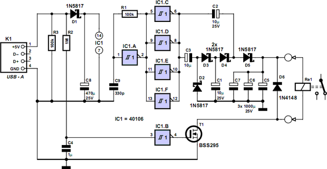
How often does it happen that a user shuts down Windows and then forgets to turn off the computer? This circuit automates that process. After Windows is shut down, a click occurs a second later, disconnecting the PC from...
This is a page of analogue interfaces for joysticks. Although these interfaces have been developed for use with 4QD's controllers, they will have plenty of other uses. Also, because of the development history, we have printed circuit boards available...
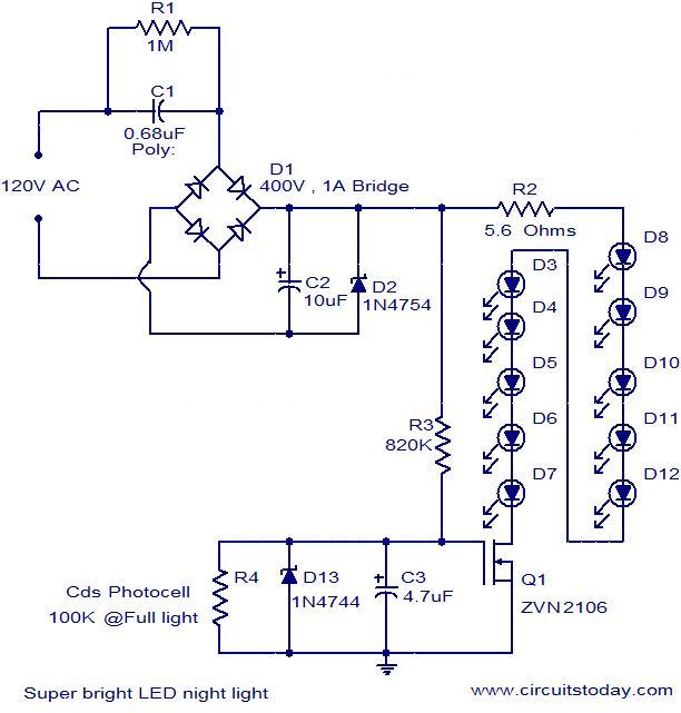
The circuit diagram illustrates a super bright LED night lamp that operates from the mains supply. A bridge rectifier (D1) is employed to convert the AC mains voltage into DC. The combination of capacitor (C1) and resistor (R1) forms...
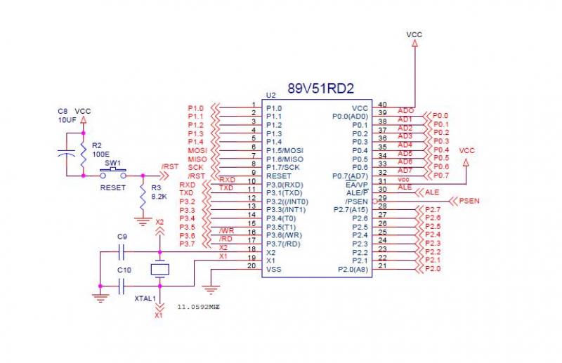
This interface session involves connecting the MCP3202 ADC with the 8051 microcontroller. The MCP3202 is a 12-bit SPI protocol ADC interfaced with the P89V51RD2 microcontroller, which supports SPI protocol, eliminating concerns about SDI, SDO, and SCK connections. The MCP3202...