
subwoofer amplifier for computer

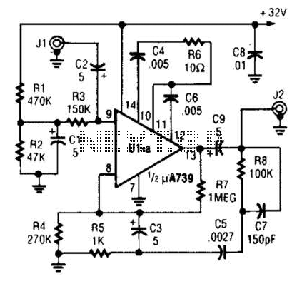
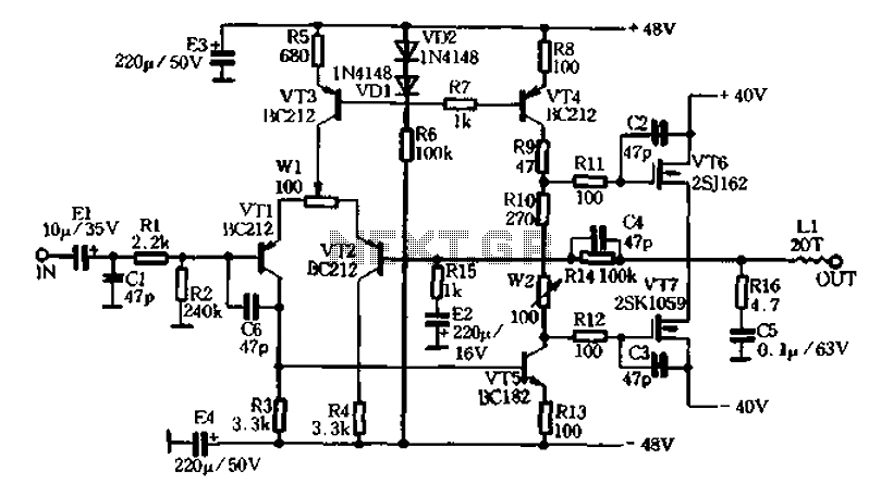
The described audio system architecture effectively addresses the limitations of conventional small speaker systems by integrating a dedicated subwoofer for enhanced low-frequency response. The K174UN14 integrated circuit serves as a crucial component in this design, providing the necessary amplification for the subwoofer while maintaining stability across the frequency spectrum. The selection of resistors R8 and R9 allows for fine-tuning of the gain, ensuring that the output meets the specific requirements of the audio environment.
The use of R10 and C6 not only establishes a frequency band for the amplification but also plays a vital role in preventing unwanted oscillations that could degrade audio quality. This design consideration is critical for high-fidelity audio applications, where clarity and precision are paramount.
The mixer stage, utilizing field-effect transistors VT1 and VT2, enhances the overall performance by isolating the outputs, thus preventing interference between channels. The amplification factor of approximately three times ensures that the subwoofer can produce a robust bass response without compromising the integrity of the audio signal. Furthermore, the adjustment provided by resistor R6 allows for a tailored listening experience, enabling users to balance the output levels of the subwoofer with the main speakers effectively.
Overall, this sophisticated audio system design exemplifies the integration of advanced electronic components to achieve superior sound reproduction, catering to the demands of modern multimedia applications.An integral part of modern multimedia computer is the presence of two active audio speakers (mounted on a monitor or set next to it). Due to a number of physical limitations of the two small computer speakers can not achieve a good reproduction of the full range of sound frequencies.
Especially collapses and distorted bass. Therefore, to obtain hi gh-quality background music is usually used yet a third column the subwoofer. In high quality active speakers, such as company Altec Lansing, a built-in audio amplifier has an output labeled SUB (model ACS40, Fig. 5. 1). It is designed to connect low-frequency active column. This circuit uses IC K174UN14 from Russia. Its gain depends on the ratio of resistors R8-R9. Chain of elements R10-C6 band of amplified frequencies limits that increases the stability of work, excluding the occurrence of generation at frequencies above 100 kHz.
Signals from the output of SUB come to the mixer, collected from field-effect transistors (VT1, VT2). Provides isolation between the mixer outputs and amplifies the signal by about 3 times. Resistor R6 sets the desired level of sound in the low column BA1 with respect to the lateral columns, and the main (overall) volume control and tone control is usually performed in the main amplifier on the body in a side column or from the program.
🔗 External reference
Related Circuits
A fundamental component for audio applications, this circuit functions as a general-purpose preamplifier. It is recommended to utilize two circuits for stereo configurations. This audio preamplifier circuit is designed to amplify low-level audio signals, making it suitable for a variety...
The power amplifier (PA) output Pi section features two variable capacitors: one ranging from 20 to 120 pF and a second, custom-built capacitor with a range of 50 to 450 pF. The latter is activated for lower frequency bands...
The circuit design features a unique technology and a reasonable structure utilizing all-discrete components with a Class A FET output. The complete circuit includes an input stage, an output stage, and a power level circuit to enhance performance, along...
A delay circuit utilizing an operational amplifier functions as a comparator, providing high timing accuracy. The timer's delay range is from 1 to 30 seconds. The delay time is determined by resistors Ri, RP, and capacitor C. By adjusting...
AURA VA50 is a company known for its production starting around 1989, marking a brief history. The launch of its products garnered attention from enthusiasts worldwide, establishing AURA's style. The company manufactured the VA amplifier series, which has been...
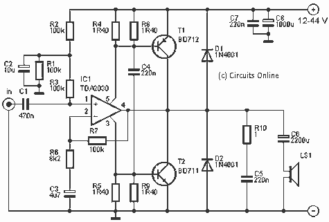
This amp delivers a lot of power and uses 1 IC and two power transistors. The circuit consists of an amplifier IC (a TDA 2030A) and a power stage consists of two transistors. The amplifier can be powered with...