
Wiring A Motor Control Electrical
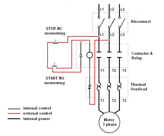
When wiring a three-phase motor using a two-pole vacuum switch, it is essential to ensure that the configuration adheres to safety standards and operational efficiency. A three-phase motor typically requires three separate phases (L1, L2, L3) for proper operation. In this scenario, the use of a two-pole switch means that only two of the three phases are being switched on and off, while one phase remains continuously connected to the motor.
This setup can lead to several potential issues. Firstly, if one phase is always hot, the motor may experience an imbalance in the phase supply, which can lead to overheating, increased wear, and reduced efficiency. Additionally, operating a three-phase motor with only two phases can cause it to run in an unbalanced condition, risking damage to the motor windings.
From a safety perspective, having one line always hot while the others are switched off can pose risks during maintenance or troubleshooting, as there is a potential for accidental contact with live components. It is advisable to utilize a three-pole switch designed for three-phase applications, which ensures that all phases can be disconnected simultaneously, enhancing both safety and functionality.
In summary, for optimal performance and safety, it is recommended to re-evaluate the current wiring configuration and consider implementing a three-pole switch that allows for complete disconnection of all phases, thereby ensuring that the motor operates under balanced conditions and reducing the risk of electrical hazards.I am wiring a three phase motor through a two pole vacuum switch. two lines go through the switch but one line is always hot to the motor. is this proper or is this a safety issue?.. 🔗 External reference
Related Circuits
Many microcontroller designs typically integrate various interfacing methods. A microcontroller (µC) system can be viewed as a system that reads from inputs. Microcontroller systems are versatile platforms that facilitate the integration of multiple interfacing methods to interact with various peripherals...
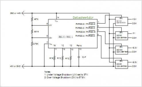
The PS10 saves board space, improves accuracy, eliminates optocouplers or level shifts, and reduces overall component count by combining four programmable timers, input under-voltage (UV) and over-voltage (OV) supervisors, a programmable power-on reset (POR), and four 90V open drain...
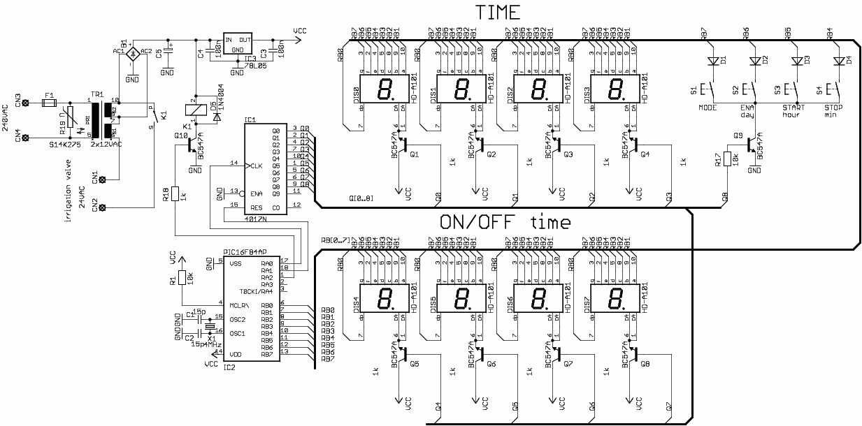
This is a simple one-valve irrigation controller made for our greenhouse. The code contains a software real-time clock (RTC) and a multiplexed 8-digit LED display and keyboard you can use in other projects. The operating software is simple, it...
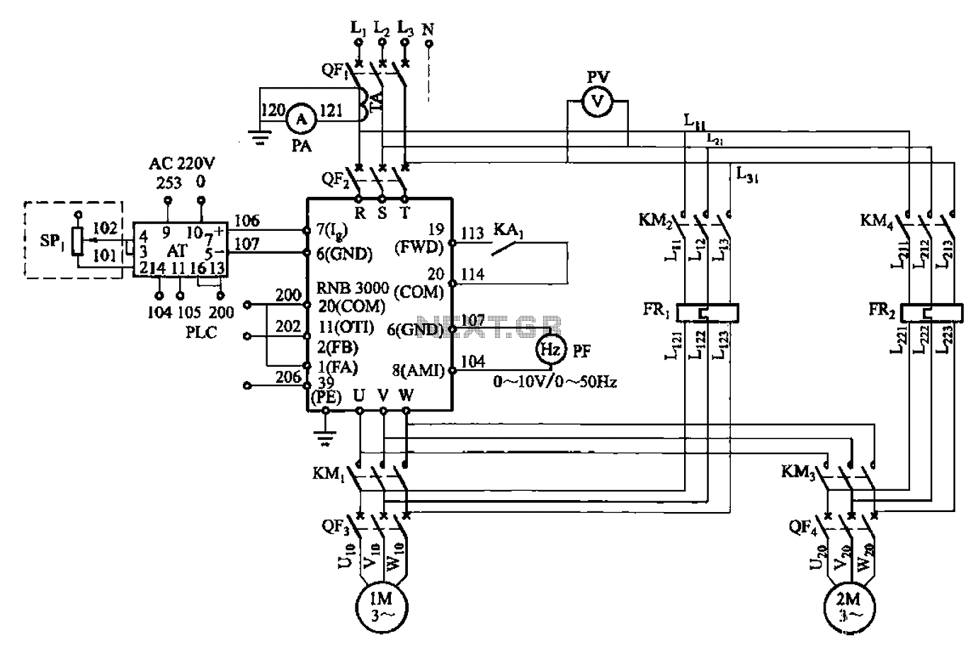
A control circuit for two motors, specifically for frequency control in a constant pressure water supply system, is illustrated in Figure 5-23. The circuit includes fault output terminals labeled 1 and 2, analog feedback current input terminals labeled 6...
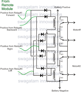
The market is filled with high-end remote-controlled toy cars; however, for hobbyists, creating one at home can be a unique experience. The following article explains how to configure a simple remote-controlled toy car using a pre-made 4-relay remote control...

This circuit represents a remote control unit that utilizes radio frequency signals to operate various electrical appliances. The remote control unit features four channels, which can be expanded to twelve. This circuit stands out from similar designs due to...
Warning: include(partials/cookie-banner.php): Failed to open stream: Permission denied in /var/www/html/nextgr/view-circuit.php on line 713
Warning: include(): Failed opening 'partials/cookie-banner.php' for inclusion (include_path='.:/usr/share/php') in /var/www/html/nextgr/view-circuit.php on line 713