
stepper motor controller

To control two stepper motors using a dsPIC microcontroller and an L298 motor driver, a specific circuit design is required. The L298 is a dual H-bridge motor driver that can control the direction and speed of stepper motors effectively.
The circuit will consist of the following components:
1. **dsPIC Microcontroller**: This will serve as the main control unit. The dsPIC will generate the control signals necessary for driving the stepper motors.
2. **L298 Motor Driver**: This IC can drive two stepper motors independently. Each motor will require two output channels from the L298 to control the direction and enable signals.
3. **Stepper Motors**: The motors will be connected to the outputs of the L298. The specific wiring will depend on whether the motors are unipolar or bipolar.
4. **Power Supply**: The L298 requires an external power supply to provide the necessary voltage and current to the motors. Ensure that the power supply specifications match the requirements of the stepper motors being used.
5. **Control Connections**: The dsPIC will output control signals to the L298. Typically, four control pins will be used for each stepper motor to manage the step sequence. These pins need to be configured as digital outputs.
6. **Enable Pins**: The L298 has enable pins that must be connected to a high logic level to activate the H-bridges. These can be controlled by the dsPIC or connected directly to a power supply.
7. **Diodes**: It is advisable to include flyback diodes across the motor terminals to protect the L298 from voltage spikes generated when the motors are switched off.
The wiring should follow the datasheet of the L298 for pin configurations. The control logic for the stepper motors can be implemented using a stepper motor control algorithm, such as full-step, half-step, or microstepping, depending on the desired precision and performance.
In summary, the circuit design involves careful planning of the connections between the dsPIC, L298, and the stepper motors, ensuring that the power supply and control signals are appropriately managed to achieve the desired motor control functionality.hi, I have 2 stepper motors to be controlled by dspic. I have programmed the pic. Im confused in usng L298 s. Can someone help me with a circuit.. 🔗 External reference
Related Circuits
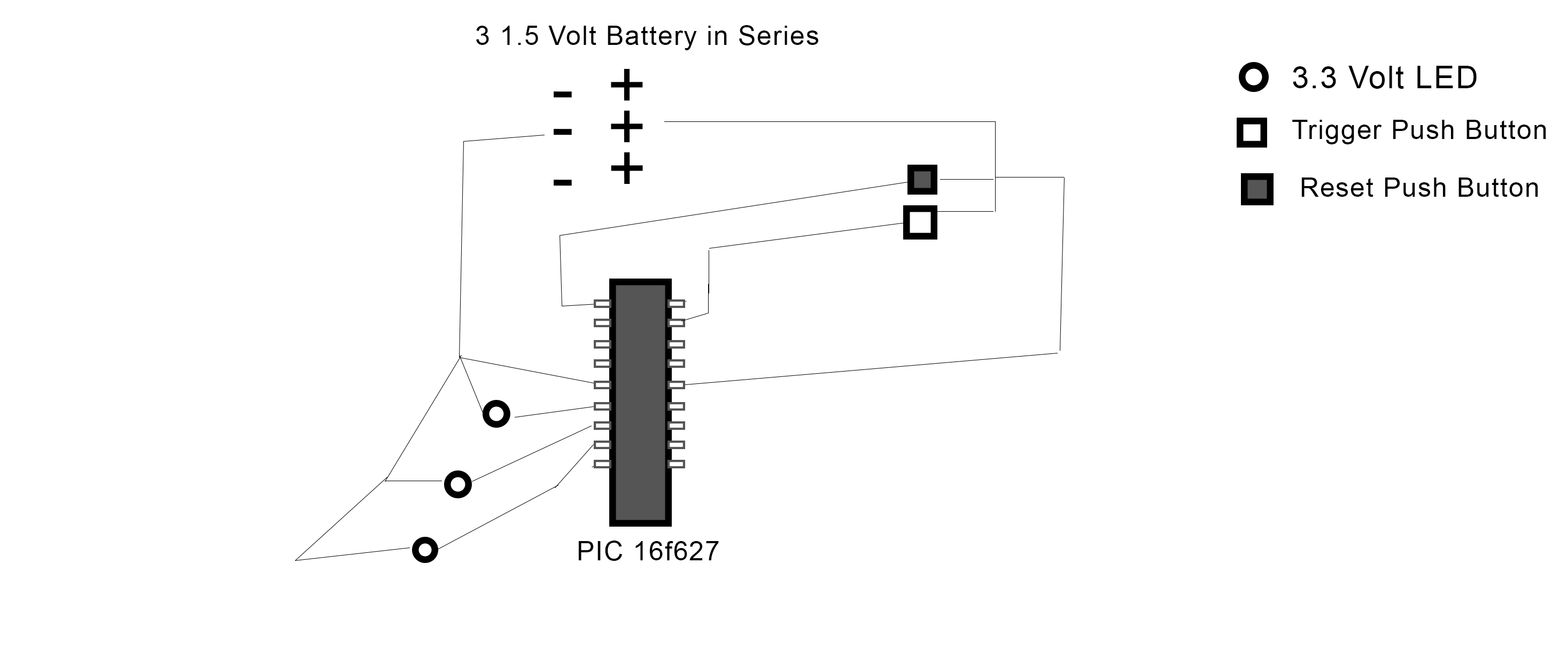
The PIC 16F627 microcontroller has been programmed to activate three LEDs when a trigger pushbutton is pressed. Additionally, when a reset pushbutton is pressed, a shutdown sequence is initiated where each LED turns off sequentially with a 5-second delay...
Nowadays, every institution requires automation. As part of college automation, a project has been developed titled "Voice Interactive System for College Automation." This project enables users to quickly access student attendance and marks through a telephone line without the...
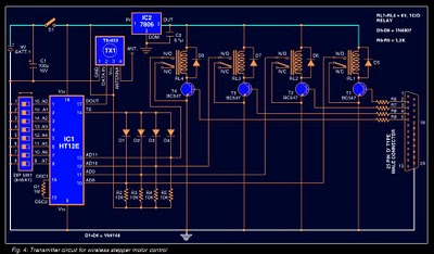
Stepper motors are widely used in applications such as process control, machine tools, and robotics. In particular, remote control of stepper motors is essential in robotics and process control. This document provides the circuit diagrams for both the transmitter...

This circuit is designed to create an early warning alarm system for any form of theft that is important to the owners of a motorcycle or bicycle. This alarm system can utilize several normally open switches, such as a...
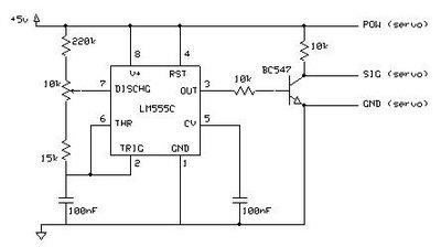
This circuit enables the testing of a servo motor. The angle of the servo can be adjusted using a 10k potentiometer. It is possible that not all positions can be achieved with this circuit; experimenting with different resistors may...
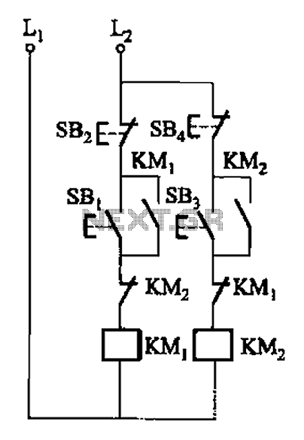
A, B, and two electric motors allow simultaneous operation through interlock control. The two motors can be connected in series with each other using normally closed contacts in the respective coil circuit. The circuit design facilitates the interlocking operation of...