
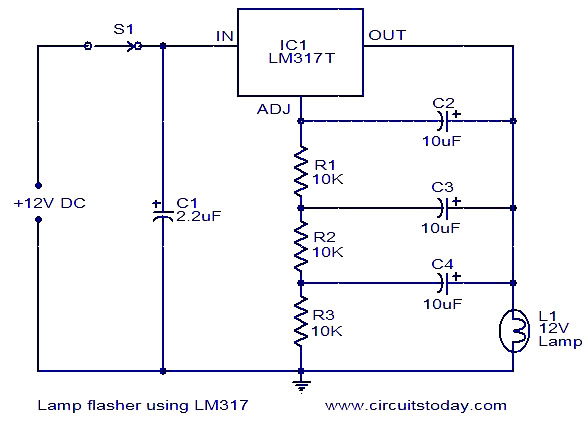
Lamp flasher using LM317
The lamp flasher circuit is designed to provide a visual signaling mechanism, commonly used in automotive lighting systems for indicators or decorative lighting. The LM317T voltage regulator is a versatile component known for its ability to maintain a steady output voltage despite variations in input voltage or load conditions. In this application, it is configured to control the flashing of the lamp.
The circuit operates by charging and discharging capacitors C2, C3, and C4 through the resistors R1, R2, and R3. The resistors and capacitors form an RC timing circuit, where the values selected dictate the charging and discharging times, thus determining the flash rate. The use of multiple resistors and capacitors allows for fine-tuning of the desired flashing frequency.
For implementation, the circuit can be powered by a standard automotive voltage supply (typically 12V). The output from the LM317T can be connected to the lamp, which will flash according to the established timing parameters. Safety measures should be taken to ensure that the circuit components are rated appropriately for the automotive environment, where vibrations and temperature fluctuations may occur.
In summary, this lamp flasher circuit using the LM317T voltage regulator is an effective solution for creating visual signals in automotive applications. The design's flexibility in adjusting the flash rate through resistor and capacitor selection makes it a valuable tool for engineers and hobbyists alike.Here is a very useful lamp flasher circuit using the famous adjustable voltage regulator IC LM317T. LM317 can source up to 1A of current and so up to 12W lamps can be used with this flasher. Such a circuit finds huge application in automobiles. The frequency of the flashing depends on the value of resistors R1 to R3 and capacitors C2 to C4. With th e given values; the flashing rate is around 5 flashes per second. 🔗 External reference
Related Circuits
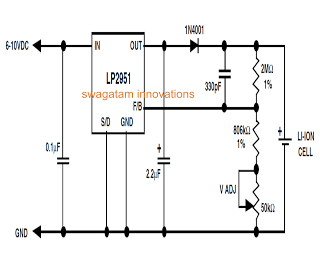
Unlike lead-acid batteries, one advantage of lithium-ion (Li-Ion) batteries is that they can be charged at a 1C rate initially. This means the charging current can be as high as the rated ampere-hour (AH) capacity of the battery at...
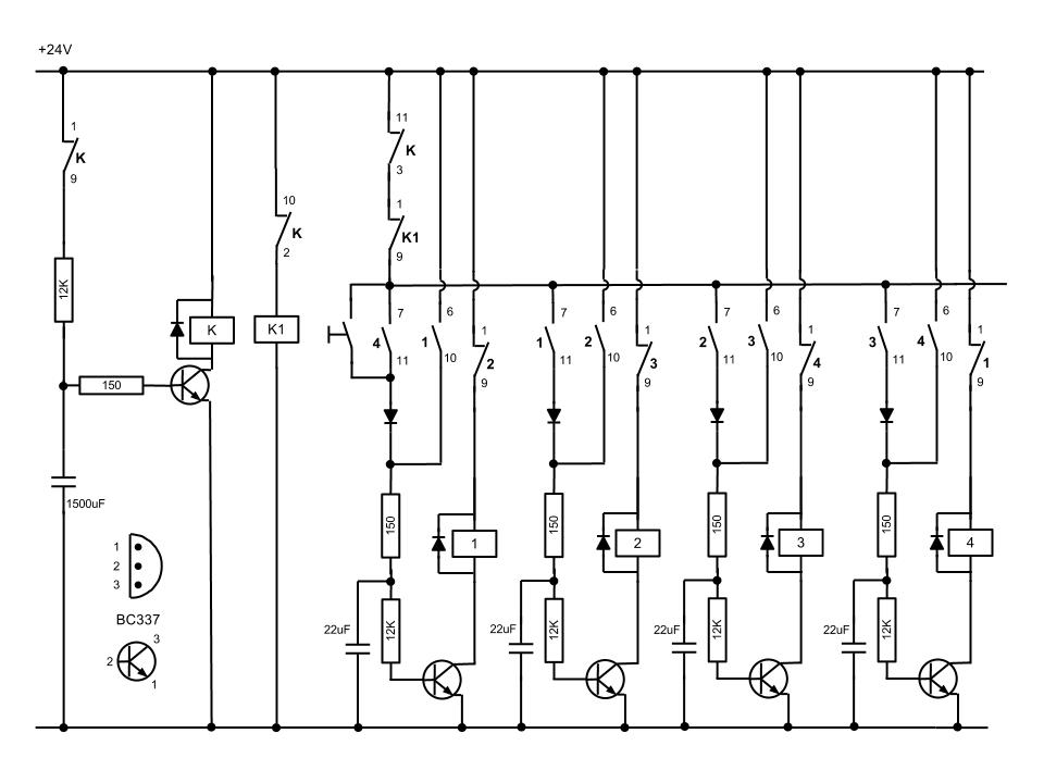
At the initial state, all pin 15 connections are grounded, causing resistor R0 to be energized. A 555 multivibrator generates a clock signal to IC1, activating the outputs from R0 to R8. This basic circuit can be employed to...
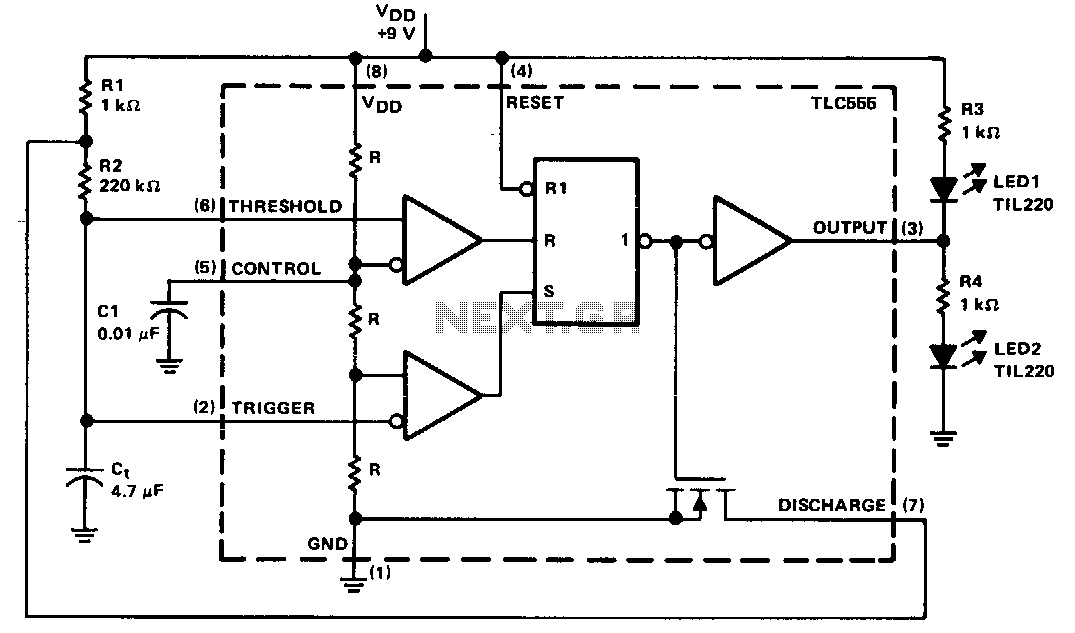
The timing components are R1, R2, and C1. C1 is a bypass capacitor used to reduce the effects of noise. At start-up, the voltage across C1 is less than the trigger level voltage (1/3 Vcc), causing the timer to...
In many countries, it is now mandatory or at least recommended to have a rear fog light on a trailer, with the additional requirement that when the trailer is attached to the vehicle, the rear fog light of the...
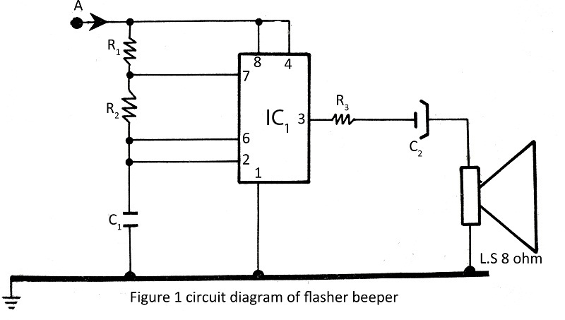
A flasher with a beeper is very easy to build and assemble. The flasher with a beeper is constructed using very common components, with various projects utilizing the NE555 timer IC. The flasher circuit typically employs the NE555 timer IC...
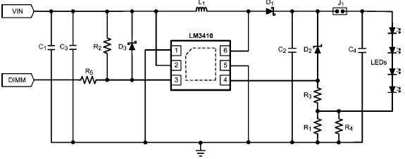
The LM3410 constant current LED driver is a monolithic integrated circuit that enables the design of high-efficiency, low-cost lighting solutions using a minimal number of electronic components. It employs current-mode control and internal compensation to ensure optimal performance across...