
Laptop Computer Power Supply Circuit

The laptop power supply circuit is designed to convert a 12-V input into a stable 9-V output suitable for powering laptop computers. This circuit employs a crowbar overvoltage protection mechanism, which is essential for safeguarding sensitive electronic components from potential voltage spikes. The crowbar circuit typically consists of a thyristor or SCR that activates when the output voltage exceeds a predetermined threshold, effectively shorting the output and protecting the load.
To ensure proper operation, the input supply voltage must be at least 3.6 V greater than the output voltage, which in this case translates to a minimum input of 12.6 V. The choice of components is crucial for reliability and performance. The transistor Q1, responsible for regulating the output voltage, must be adequately heatsinked to dissipate heat generated during operation. This is particularly important in high-current applications where thermal management can significantly impact component longevity.
Resistor R5 plays a vital role in setting the output voltage. For the specified 9-V output, R5 should be calibrated to a value of 1.5 ohms, which helps establish the appropriate feedback for the voltage regulation circuit. The circuit may also include additional resistors and capacitors to enhance stability and transient response.
It is essential to consider the output voltage ratings when selecting capacitors. Any output voltage exceeding 10 V will require an input voltage greater than 13.6 V, necessitating the selection of capacitors with higher voltage ratings. A general rule of thumb is to allow a minimum of 2.5 times the expected voltage across the capacitor for its working voltage rating. This precaution ensures that the capacitors can handle voltage spikes without failure, thereby enhancing the overall reliability of the power supply circuit.
In summary, the described laptop power supply circuit combines voltage regulation, overvoltage protection, and thermal management to deliver a stable output while adhering to safety standards and component specifications. A laptop computer supply that has 9-V output, crowbar overvoltage protection, and operates i`rom a 12-V supply is shown above. The supply voltage should be at least 3.6 V above the expected output voltage. Ql should be heatsinked appropriately. R5 should have a value of 1.5 1: for 9-V output. Table 1 gives values for other voltages. Note: Any output voltage value greater than 10V requires a higher input voltage than 13.6V. In addition capacitor working voltage ratings will have to be increased accordingly. Allow a minimum of 2.5 times the voltage expected to appear across the capacitor as a standard for the working voltage.
Related Circuits
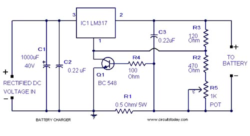
A simple lead-acid battery charger circuit with a diagram and schematic using the IC LM317, which provides the correct battery charging voltage. This lead-acid battery charger should be supplied with an input of 18 volts to the IC. The lead-acid...
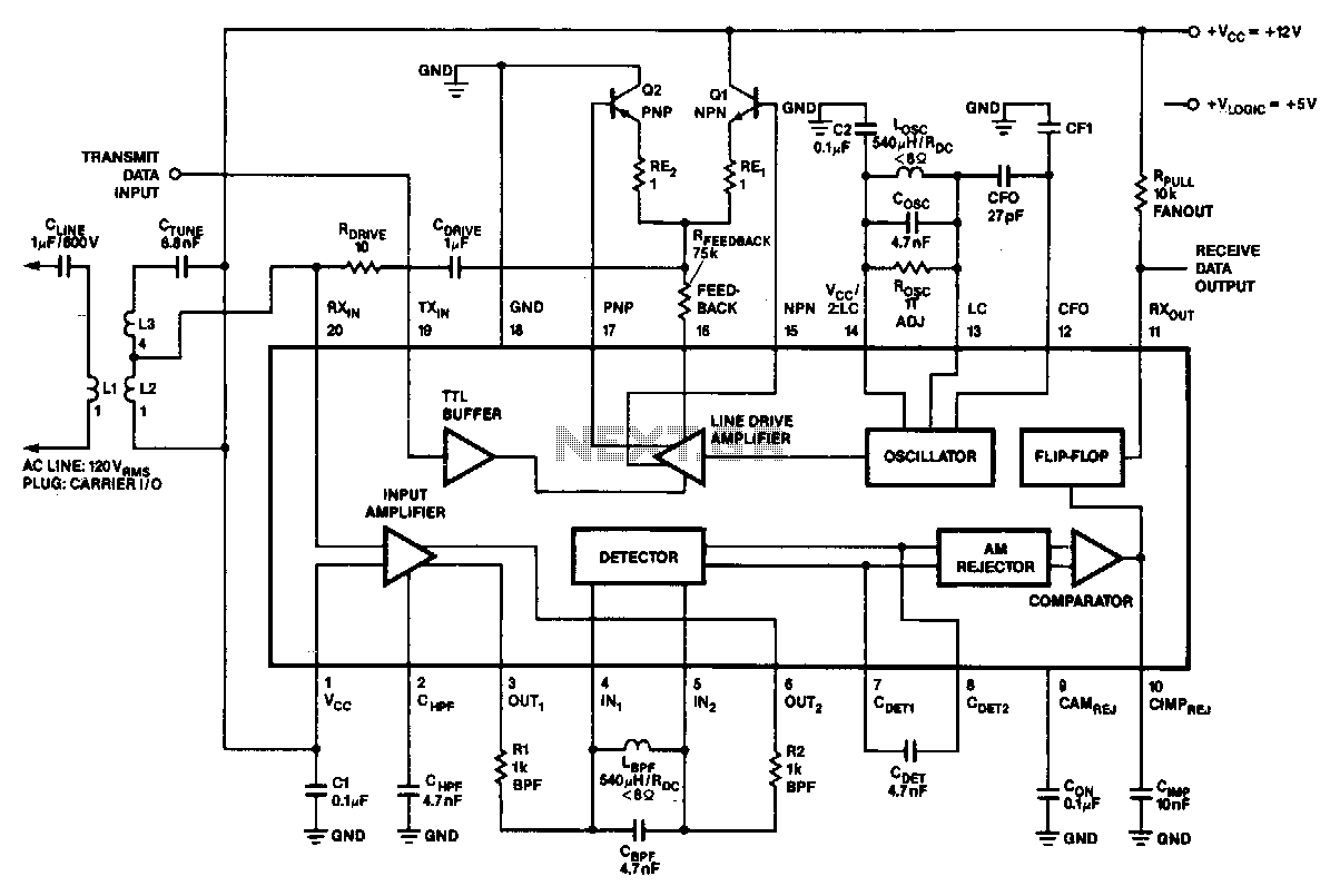
In the 100-kHz application, the coupling network feeds into the receiver section located at the bottom of the chip. The external components are summarized later. The receive data output is pulled up via a resistor (RPuLL) of approximately 10...
This circuit will allow you to connect any tape recorder that has a mic and remote input to a phone line and automatically record both sides of a conversation whenever the phone is in use. You will need to...
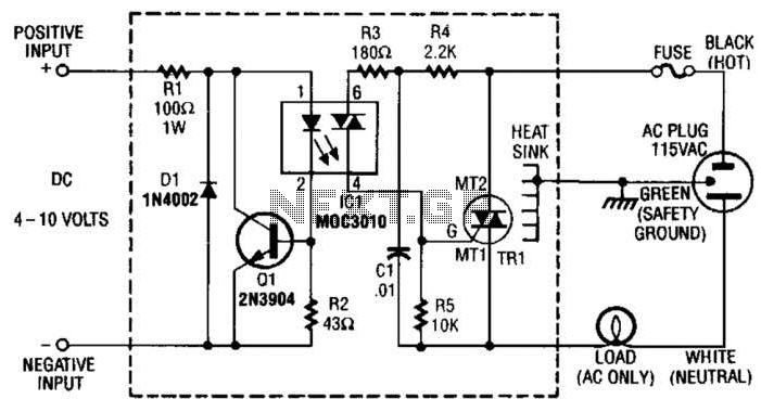
Rl limits input current while Ql acts as a current sink to protect IC1. D1 serves as a polarity protector. IC1 provides a triac output to trigger the main triac, TR1. The circuit consists of several key components that...
U1 is the 3817 integrated circuit, capable of directly driving the display. It can show time in either 12-hour or 24-hour format, schedule alarm sounds, and automatically turn on the radio at specified times. The display utilizes the FND500...
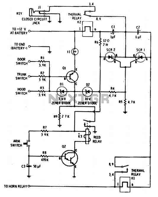
The car alarm is a straightforward circuit with fundamental features that monitor all entry points of the vehicle, such as doors, using switches. It operates with a single switch (the arm switch) that allows the circuit to remain inactive...