
laser sup circuit
The circuit design for a high voltage power supply for laser tubes typically involves a few key components: a transformer, a rectifier, a filter capacitor, and a current-limiting resistor. The transformer, a 9V 1A unit, is connected in reverse to step up the voltage to the required levels for the laser tube operation. The output from the transformer is AC, which must be converted to DC using a rectifier, commonly a diode bridge configuration, to ensure a steady supply of current.
The filter capacitor serves to smooth out the rectified voltage, reducing ripple and providing a more stable DC output. The value of this capacitor can vary depending on the specific requirements of the laser tube and the desired performance characteristics.
Resistor R2 plays a critical role in protecting the laser tube from excessive current. It should be soldered directly to the anode terminal of the laser tube, and its value must be carefully selected. Starting with a 500K 10W resistor is advisable, and the resistance should be adjusted downward until the laser tube lights up consistently without flickering, indicating a stable operation.
It is essential to consider the specifications of the transformer being used, as variations in the number of secondary windings can significantly affect the circuit's performance. Transformers with fewer windings may saturate quickly, leading to a loss of efficiency and potentially damaging the circuit. Therefore, selecting a transformer with a higher number of secondary windings is recommended to achieve optimal performance.
This circuit should be assembled with caution and thorough testing, as the high voltage involved can pose safety risks. It is advisable to take necessary precautions, such as using insulated tools and wearing appropriate safety gear when working with high voltage electronics.If you have ever worked with lasers, you know how fun and interesting it can be, you also know how expensive it can be. The high voltage power supplies for the laser tubes are often more expensive then the tubes themselves.
This supply can be built with commmon parts, most of which you probably already have in your junk box. The secret is the tran sformer used. It is a common 9V 1A unit, connected backwards for step up. Please note that some people may have trouble with this supply. This is due to the slight difference in transformers. For more information on LASER power supplies, take a look at Sam Goldwasser`s Laser Supply Info Page. R2 Protects the laser tube from excess current. It should be soldered directly to the anode terminal on the tube. To find R2, start with a 500K 10W resistor and work down until the tube lights and remains stable. Depending on the transformer you use, the circuit may or may not work. I cannot guarantee the operation of this circuit. Build at your own risk. Some transformers contain very few secondary windings which will quickly saturate the core and basically act like a direct short.
The more secondary windings (that is, primary in this circuit) the better. 🔗 External reference
Related Circuits
Many individuals who invested in Prologic decoders are now considering Dolby Digital technology. New formats such as DSS, DVD-Video, and High Definition Television incorporate this technology; however, the older laserdisc format also deserves attention, as over 600 laserdiscs feature...

This circuit describes the sensing of air flow using the PIC16C781 microcontroller. It utilizes Programmable Switch Mode Controllers (PSMC) that combine an Integrated Operational Amplifier, a Digital-to-Analog Converter (DAC), and a gated timer to create a thermally operated air...
This month I am making 3 different types of siren circuits based on the 555 timer. The first circuit simulates the siren of a British police car. It uses two 555 timers in the circuit. The 555 on the...
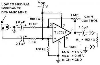
The schematic diagram of a microphone preamplifier is based on the operational amplifier TC251. The TC251 operates with low bias and functions with a supply voltage of only 1.5 V, drawing an electric current of just 10 mA, making...
The wireless remote control transmitter circuit consists of control buttons S1 to S16, resistors R1 to R3, a capacitor C1, a regulator diode VS, a crystal oscillator BC1, and DTMF encoder integrated circuits IC1 and IC2. The circuit components...

This is a design circuit for an alarm. This circuit is intended for an anti-theft wireless alarm that can be used with any vehicle operating on a 6 to 12 volt DC supply system. A mini VHF FM radio-controlled...