
gear display

The universal digital gear display is designed for easy installation on a variety of motorbike models, providing riders with a clear indication of the current gear engaged. The device utilizes basic Transistor-Transistor Logic (TTL) technology, which is known for its reliability and cost-effectiveness. The absence of complex software programming simplifies the setup process, making it accessible for users without extensive technical knowledge.
The schematic for this gear display includes several key components. A microcontroller, capable of interpreting signals from the motorbike's gear selector, serves as the central processing unit. The microcontroller is connected to a series of light-emitting diodes (LEDs) that visually represent each gear.
To enhance functionality, the circuit may incorporate a voltage regulator to ensure stable operation across varying input voltages from the motorbike's electrical system. Additionally, a series of resistors and capacitors may be included to filter signals and prevent noise interference, ensuring accurate gear detection.
The user interface consists of a simple display panel mounted on the motorbike's dashboard, allowing for easy visibility while riding. This design prioritizes user safety and convenience, ensuring that the rider can quickly ascertain the gear status without distraction.
In summary, this universal digital gear display represents a practical solution for motorbike enthusiasts seeking an efficient and economical method for gear indication, leveraging straightforward TTL technology to deliver reliable performance.A universal digital gear display that can be installed on any motorbike. A low cost solution based on simple TTL digital technology without software programming.. 🔗 External reference
Related Circuits

This design explains how to use an encoder to set the number shown by a 7-segment display. Turn the knob clockwise to increment the number, turn it counterclockwise to set it back. Encoders are the most practical way to...
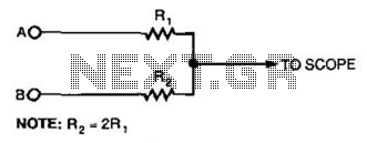
This simple resistor circuit can be used to trick an oscilloscope into displaying two logic signals on one channel. By selecting R2 to be twice the value of R, the oscilloscope trace will show one of four distinct analog...
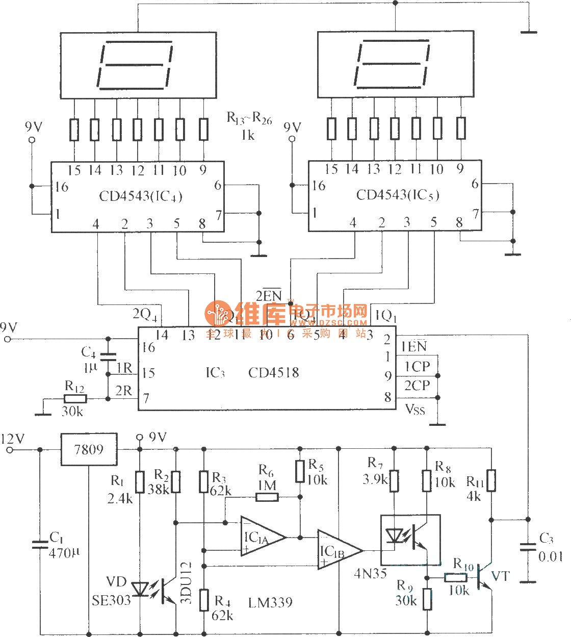
The circuit includes an optical input circuit (VD, 3DU12), a pulse forming circuit (IC1A, IC1B functioning as a voltage comparator; optical coupler; transistor switching circuit), and a counting and display circuit. The circuit architecture consists of several key components that...
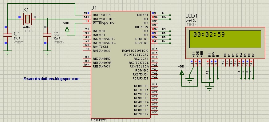
This tutorial on the PIC16F877 microcontroller addresses the question, "How to implement a digital clock using the PIC16F877?" The use of the PIC16 simulator (Proteus) is included. The PIC16F877 microcontroller is a versatile and widely used component in embedded systems,...

The 040904C version of the code has a larger UART receive buffer and supports two pushbuttons that send either an ASCII "R" ($52) or an ASCII carriage. Something to keep in mind when using AVR controllers that support 16-bit...
Each step will result in a self-functional unit. By the end of this process, it will be possible to link the steps together into a powerful FM transmitter. This section will explain the main controlling unit for the FM...