LC Meter

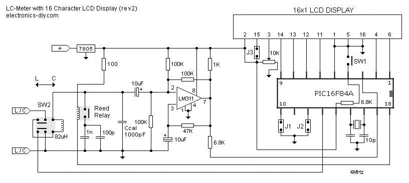
A circuit for an LC meter (inductance and capacitance meter) based on the PIC16F84A microcontroller. However, there is no code available for this microcontroller. A circuit diagram of the project is provided for assistance.
The LC meter circuit utilizes the PIC16F84A microcontroller, which is a popular 8-bit microcontroller from Microchip Technology. This microcontroller is known for its versatility and ease of use in various electronic applications. The primary function of the LC meter is to measure the inductance of coils and the capacitance of capacitors, providing valuable information for electronics enthusiasts and engineers.
The circuit typically comprises several key components: the PIC16F84A microcontroller, an oscillator circuit, a display unit (often an LCD or 7-segment display), and additional passive components such as resistors and capacitors. The oscillator circuit generates a stable frequency signal, which is then used to determine the values of inductors and capacitors connected to the circuit.
In operation, the LC meter applies a known frequency to the component under test. The microcontroller measures the frequency response of the component, allowing it to calculate the inductance or capacitance based on the change in frequency. The results are then displayed on the output unit, providing the user with real-time measurements.
For optimal performance, proper calibration of the LC meter is essential. Calibration involves using standard inductors and capacitors to ensure that the readings are accurate. Additionally, the circuit design should minimize noise and interference to enhance measurement precision.
The provided circuit diagram will illustrate the connections between the components, including power supply connections, input/output pins of the microcontroller, and the arrangement of passive components. Proper layout and grounding techniques should be employed to ensure reliable operation of the circuit.
In summary, the LC meter circuit based on the PIC16F84A microcontroller is a valuable tool for measuring inductance and capacitance, and careful attention to design and calibration will yield accurate and reliable results.A circuit of LC meter (inductance & capacitance meter) which is base on PIC16F84A microcontroller but i have no code for this IC, i place circuit diagram of the project, so please help me. 🔗 External reference


