
LCD monitor Switched Mode Power Supply
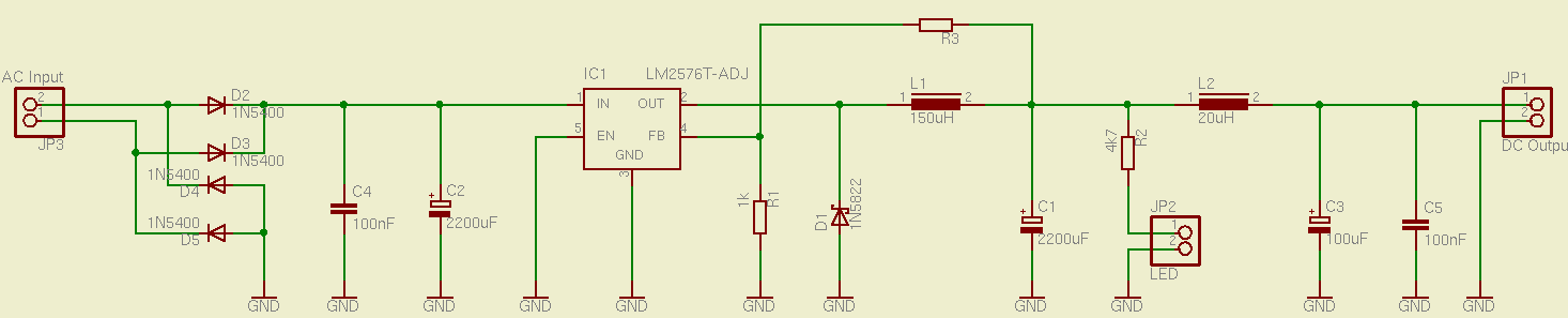
The switched mode power supply (SMPS) described utilizes the LM2576-ADJ voltage regulator, which is a versatile and efficient component for DC-DC conversion. This regulator is part of the buck converter family, allowing for step-down voltage regulation. The adjustable output voltage feature is particularly beneficial, as it provides flexibility for various applications beyond the specified 20V at 2.3A for the LCD monitor.
In the schematic, the LM2576-ADJ is configured with a feedback loop that includes the variable resistor R3, enabling output voltage adjustment. The inductor plays a critical role in energy storage and transfer during the switching cycle, contributing to the overall efficiency of the power supply. The output capacitor smooths the voltage, reducing ripple and ensuring stable operation under varying load conditions.
The choice of a toroidal inductor enhances efficiency due to its lower electromagnetic interference and better magnetic properties compared to other inductor types. The design's single-layer PCB layout simplifies manufacturing and assembly while maintaining adequate thermal and electrical performance. The wide traces are essential for minimizing voltage drop and heat generation in high current paths, ensuring reliability and longevity of the power supply system.
Overall, this SMPS design exemplifies a practical approach to power supply design, emphasizing efficiency, adaptability, and the use of salvaged components, making it a valuable solution for powering electronic devices.This is a simple and effective switched mode power supply (SMPS) that I built to power a LCD monitor that I fixed a while ago. This one requires 20V at 2. 3A, but the PSU output voltage can actually be set in the range 1. 2V - 25V, with a small variable resistor (R3 in the schematic below). It uses a LM2576-ADJ regulator which requires very few exte rnal parts and as you can see from the schematic of figure 1. I didn`t go much far from the bare application example, that you can find in the National Semiconductor datasheet. There you can also find the required calculations necessary to obtain all the part values that surround the regulator, in particular the coil inductance and output capacitor.
The regulator can sustain 3A output current which is more than enough for the required 2. 3A of the LCD. It uses the simple buck-converter topology which allows to obtain a fairly stable and regulated output voltage. The switching mode approach dictates a much better efficiency than the linear regulator normally used in simple circuits.
I designed a simple one layer PCB layout, with wide traces for the paths where the current is substantial, maybe too wide ;) (see figure 2. ) You can get both the schematic and PCB in the Eagle file format from here. In figure 3. and 4. you can see the power supply already assembled and with the load (monitor) applied. You can notice the big yellow switching toroidal inductor. I got its core from a broken PC power supply and patiently winded the dozens of turns with wire I had laying around.
The remaining parts I salvaged from the junkbox, except the regulator which I bought from an online electronics distributor. 🔗 External reference
Related Circuits
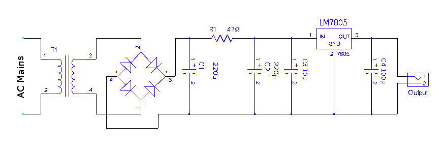
A regulated 5-volt DC supply is essential for powering microcontroller and TTL-based circuits. The output of most wall adapters is often too rippled and impure for use in digital circuits. An inexpensive power supply can be constructed using discrete...
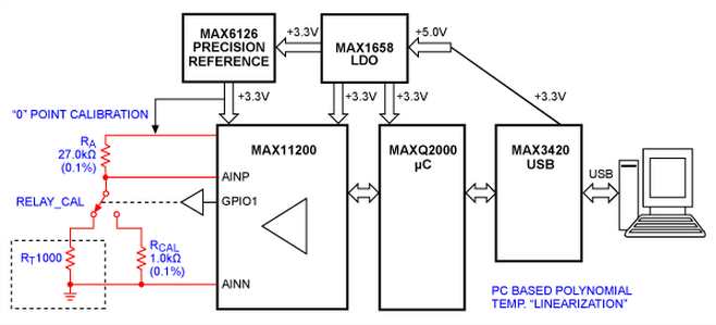
This article explains how platinum resistance temperature detectors (PRTDs) can perform measurements over wide temperature ranges of -200 °C to +850 °C, with absolute accuracy and repeatability better than ±0.3 °C, when used with modern processors capable of resolving...
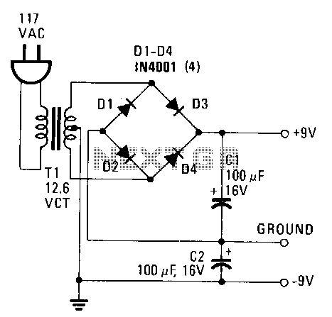
This power supply provides both +9 V and -9 V outputs to replace two 9-V batteries. The rectifier circuit consists of two separate full-wave rectifiers, each connected to the secondary winding of the transformer. The first full-wave rectifier, made...
A dimmer switch is an electrical device that can replace standard switches used for lamps, heaters, or certain types of electric motors. Dimmer switches allow for the adjustment of light intensity and power levels. Dimmer switches operate by varying the...
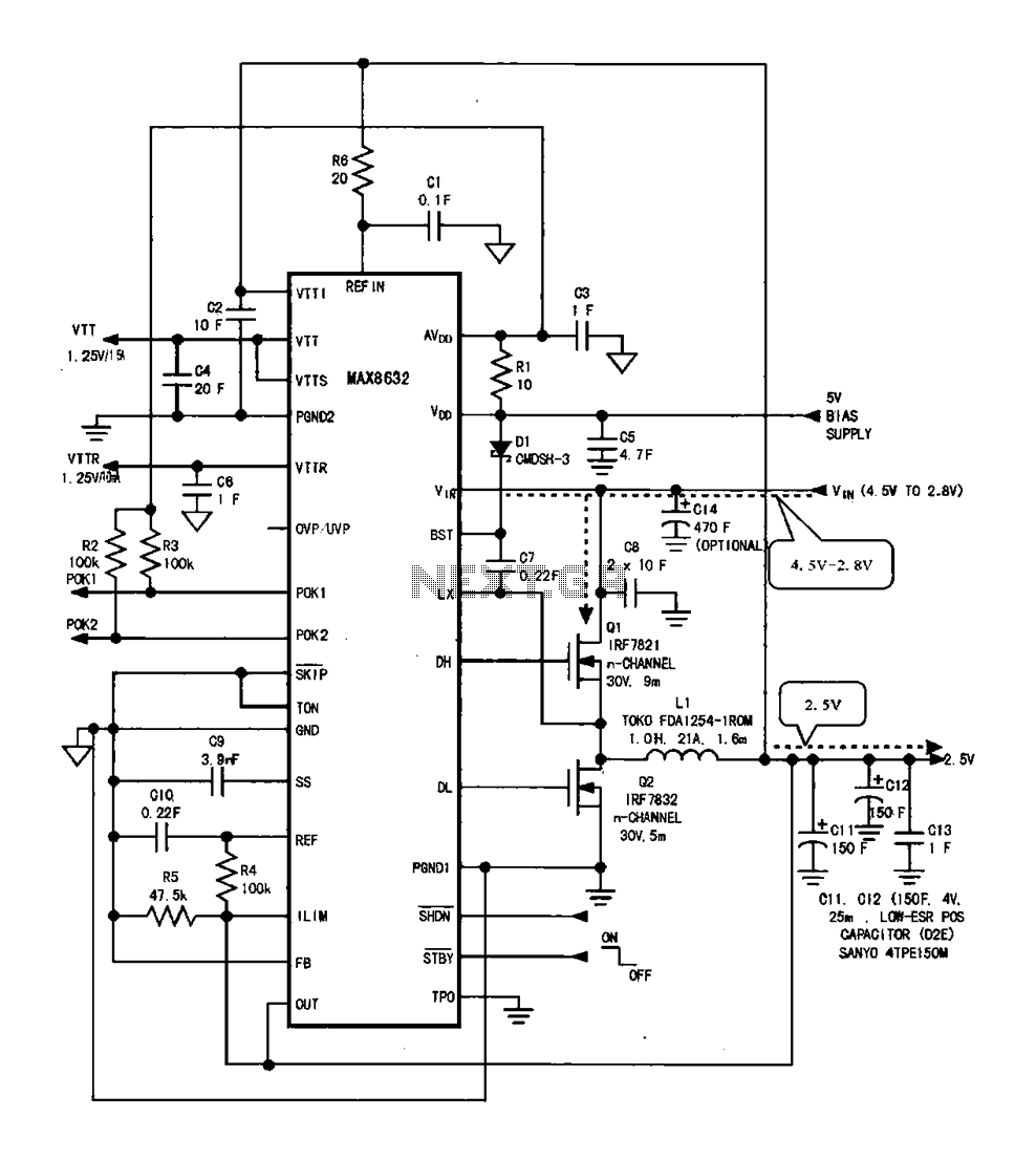
DDR memory power supply circuit. This circuit illustrates the power supply configuration for notebook DDR memory, utilizing the MAX8632 power control circuit chip. The power supply terminal VDD is connected to the voltage detection point 1. The battery DC...
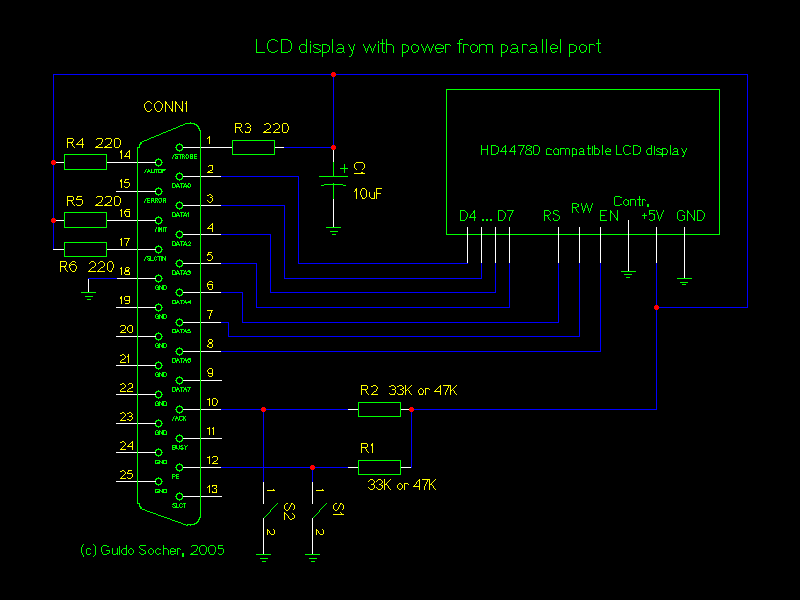
This example implements a clock using 36 lines of Perl code. It displays the time and date, with a small icon called "heartbeat" in the upper right corner. The "heartbeat" icon, added by the LCDd server, blinks intermittently to...