
temporary led lampilluminator circuit

The temporary lamp circuit is a straightforward yet effective design that addresses the need for brief illumination in various situations. The core components of the circuit include a push button switch (S1), a capacitor (C1), and a small NPN transistor. The operation begins when the push button is pressed, allowing current to flow and charge the capacitor C1. The capacitor serves a dual purpose: it not only stores energy but also provides the necessary bias current to the base of the transistor.
The choice of the capacitor value directly influences the duration for which the LED remains lit. A standard value of 10µF provides approximately 10 seconds of illumination, but increasing the capacitance to 47µF or 100µF will extend this duration, allowing for longer tasks to be performed without the need to re-press the button. This adaptability makes the circuit versatile for various applications.
The transistor's role in the circuit is crucial, as it acts as a switch that controls the LED. When the base current from the capacitor is sufficient, the transistor enters saturation, allowing current to flow through the LED, illuminating it. The circuit is designed to handle LED currents up to 20 mA, making it suitable for a wide range of standard LEDs.
In summary, this temporary lamp circuit is a practical solution for situations requiring short-term lighting. Its simplicity, combined with the ability to adjust the illumination duration through capacitor selection, makes it an excellent choice for emergency lighting or quick tasks where hands-free operation is beneficial.Here`s a design circuit for temporary lamp circuit is very helpful in emergency situation or in any application where we don`t have much time to turn off the lamp. Just press the push button, do a little fast task, and then leave it. This circuit hold the LED light for about 10 seconds, which should be enough for most simple tasks. This is the fig ure of the circuit; This circuit works like this: when the push button S1 is pressed, the C1 will be fully charged instantly. Not only charging the capacitor, the current will supply the bias current for transistor`s base as well.
This base current will activate the transistor to turn on the LED. After the push button is depressed, the capacitor C1 will keep supplying the base current for about 10 seconds, holding the LED lamp on. If you think this period is too short then you can try with different C1 values, try 47uF or 100uF and you`ll see the difference.
You can use almost any type of small transistor since almost all small transistors will be capable of driving LED lamp which draw current less than 20 mA. 🔗 External reference
Related Circuits
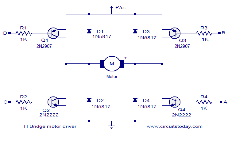
The circuit presented is a simple H-bridge motor driver circuit utilizing commonly available components. An H-bridge is an efficient method for driving motors and is widely used in various electronic projects, particularly in robotics. The circuit illustrated is a...
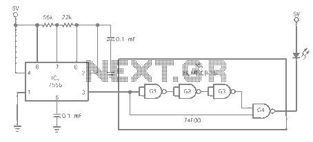
The entire series of TTL monostable multivibrators lacks sufficient speed, prompting the need for an ECL voltage swing that accommodates a wide range of small power requirements. This necessitates the use of F series circuits, which offer fast transition...

The LM111/211/311 power supply operates within a voltage range of 5V to 15V. It features bias current, offset current, and a differential input voltage range of 30V. The output is compatible with TTL, DTL, and MOS circuits, allowing it...

Four simple 12V power supply circuits are designed to provide output voltages close to 12V. The first power supply circuit utilizes a BD139 transistor, a zener diode, and several passive components. Each schematic is straightforward to assemble and will...
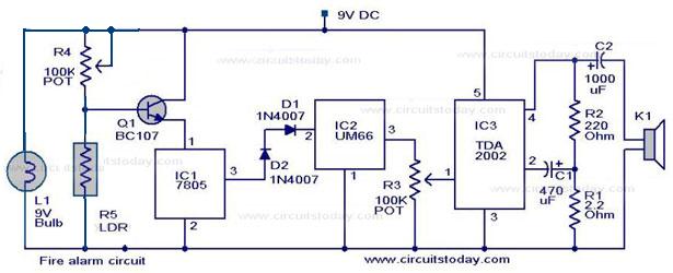
A simple fire alarm circuit utilizes a light-dependent resistor (LDR) and a lamp for smoke detection. The system operates by detecting smoke generated during a fire. An audible alarm is triggered when smoke is present. In the absence of...
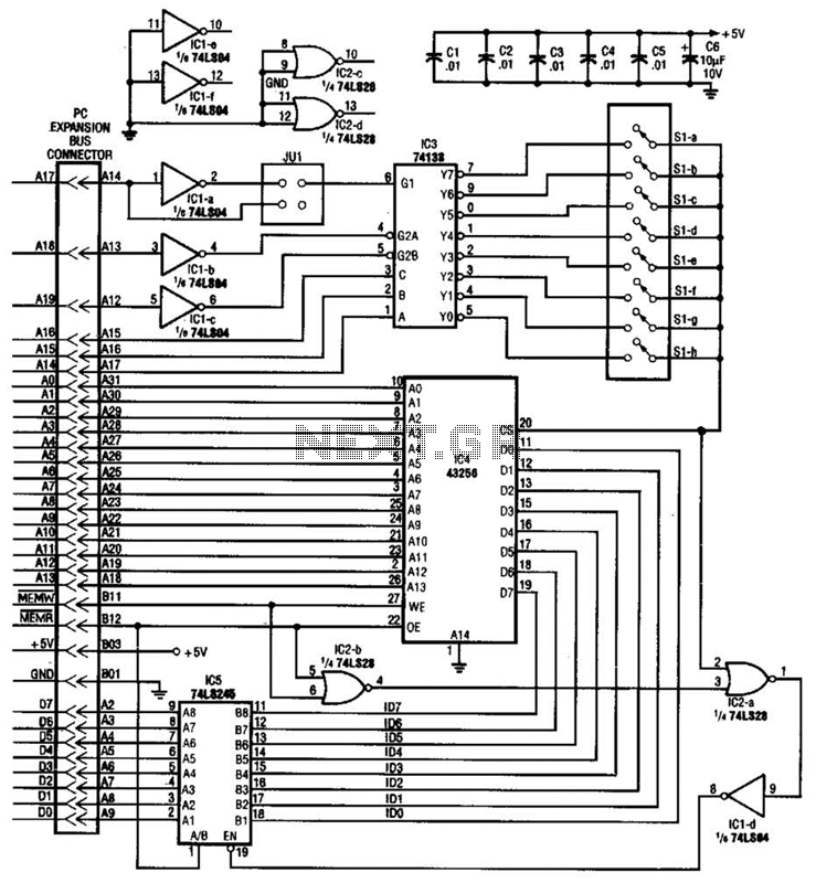
This circuit protects a PC by requiring a password to boot. After three unsuccessful attempts, the computer must undergo a cold reboot before the password can be attempted again. Software for this system is available; consult the reference for...