
LED driver based on MP3302 LED driver IC. Working circuit diagram.Operates from a single Lithium ion battery
The MP3302 integrated circuit is engineered to provide efficient and reliable LED driving solutions, particularly in applications where space and power efficiency are critical. The use of internal MOSFETs minimizes the need for external components, simplifying the design and reducing overall circuit size. The constant current mode ensures consistent brightness across all LEDs, which is essential for applications such as backlighting in displays or general illumination.
The PWM dimming feature allows for versatile control over LED brightness, enabling designers to implement various lighting effects or adapt the brightness based on ambient light conditions. The inclusion of safety features such as thermal shutdown and open load protection enhances the robustness of the design, making the MP3302 suitable for a wide range of environments and applications.
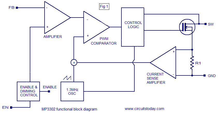
Incorporating the MP3302 into LED driver designs facilitates the creation of compact, efficient, and reliable lighting solutions, catering to the growing demand for energy-efficient lighting technologies. The flexibility of the IC to operate across different supply voltages and its capability to drive multiple LED strings make it a valuable component in modern electronic lighting applications.MP3302 is a boost converter IC specifically designed for LED drive applications. The MP3302 can drive 27 LEDs (9 strings of 3 white LEDs in series) from a Lithium ion battery. The IC has internal power MOSFETs for driving the LEDs and has an efficiency of 88%. Switching frequency is 1. 3MHz and the internal current limit is 1. 33A. Other features of the MP3302 are open load shut down, thermal shut down, under voltage lock out etc. Applications of Mp3302 are LED back lights, LED based lighting gadgets etc. Functional block diagram of the MP3302 is shown below (Fig1). The IC uses a constant current, peak current mode step up regulator scheme for regulating the current through the LEDs. At thebeginning of each oscillator cycle, the control circuitry switches the power MOSFET ON. For preventing sub harmonic oscillation, a stabilizing ramp signal is added to the current sense amplifiers output and the resultant signal is given to the non inverting input of the PWM comparator.
When this resultant voltageis equal to the voltage at the PWM comparator`s inverting input (output voltage of the error amplifier), the power MOSFET is switched OFF. The error amplifier`s output is the difference between the feedback voltage and the reference voltage.
When the output voltage drops, the feedback voltage also drops and this in increases the output of the error amplifier. This in turn increases duty cycle of the power MOSFET drive signal produced by the control circuitry which increase the duty cycle of the power MOSFET, it conducts more current and the output voltage is regulated.
Circuit diagram of a 27 LED driver circuit using MP3302 is shown below (Fig 2). C1 is the input bypass capacitor and C2 is the output bypass capacitor. Resistor R1 is the feedback resistor and it controls the LED current. The governing equation is: LED current = 195mV /R1. Resistors tagged R are the current limiting resistors for the corresponding strings and they can be used forlimitingthe maximum brightness of the LEDs. A voltage level less than 0. 4V to the EN pin will shut down the IC and a voltage level greater than 0. 7V will enable the IC. Dimming of the LEDs can be achieved by providing a PWM signal in the range of 200Hz to 1KHz to the EN pin.
The absolute minimum amplitude of the PWM signal is 1. 5V. The built in open load protection circuit will shut down the IC when ever the output voltage goes above 38V. The IC will remain in the shut down mode until the power supply is re switched. The figure shown below (Fig 3) is of an LED driver circuit that can be operated from a wide supply voltage range (3.
3V to 18V). This circuit too is based on the MP3302 LED driver IC. An extra bias circuit comprising of resistor R and Zener diode D is added inorder to make the ON resistance of the power MOSFET low and make the chip compatible to high input voltages. This circuit can drive 3 parallel strings of 9 white LEDs in series. Remaining part of the circuit is similar to the LED driver shown in Fig 2. Circuit diagram of a fixed frequency LED driver using MP3302 led driver IC is shown in the diagram (Fig4) below.
The circuit can drive a string of 10 white LEDs in series. The basic operation of this circuit is also similar to that of the LED driver shown in Fig 2. Another LED driver circuit based on the MP3302 LED driver IC. This circuit can drive 9 parallel strings of three white LEDs in series and can be operated from a 3V DC supply and it is suitable for single cell applications. 🔗 External reference
Related Circuits
It is the essential continuity of circuits Sel 8 Sources and Up/Down Sel 8 Sources, but can work and autonomously, collaborating with any suitable circuit of control. The Relay 1-8 can be 6-24v DC. For current of collector of...
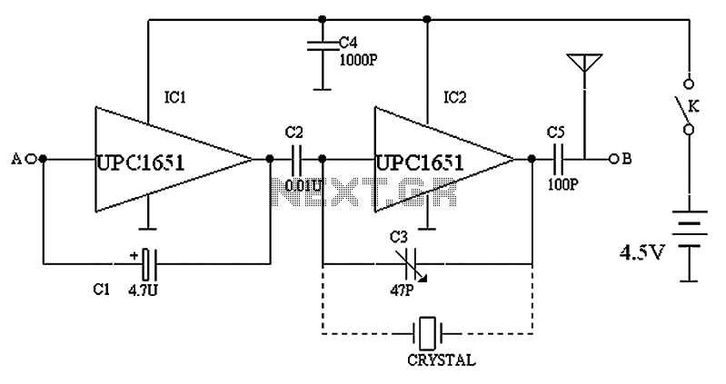
The circuit depicted in the figure includes IC1 and C1, which form a low-frequency oscillator operating at approximately 400 Hz. IC2 and C3 are configured to create a frequency oscillator around 37 MHz. The low-frequency signal is output from...

The TDA1072AT is a specialized integrated circuit designed for AM radio receivers, produced by Philips Semiconductors. This IC is intended for use in both mains-fed home receivers and car radios. It features a voltage-controlled oscillator that delivers signals with...
The controllable multivibrator, as illustrated in figure 14-40, consists of a 555 timer along with resistors RA, RP1, and capacitor C1. The oscillation frequency is influenced by the control voltage applied to pin 5. This control voltage is determined...
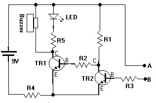
This document presents a water sensor circuit designed to monitor soil moisture levels for plants. This circuit is straightforward and is constructed using five resistors, two transistors, an LED, a buzzer, and a battery. The operation of the circuit...
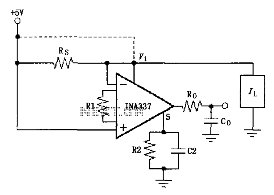
The INA337 circuit, as illustrated, is part of a load current measuring shunt circuit. It generates a voltage drop across the sampling resistor Rs, which is connected in series between the power source and the load. The load current...