
A Phase Controlled Triac (HT-32)
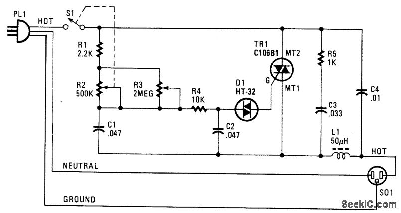
The Phase Controlled Triac circuit, utilizing the HT-32 component, is designed for applications requiring precise control of AC power. The circuit primarily consists of a Triac, which is a semiconductor device that can control the power flow in AC circuits by switching on and off at specific points in the AC waveform. The phase control method allows for the adjustment of the output voltage by delaying the triggering of the Triac.
In this circuit, bilateral trigger diacs are employed to ensure that the Triac can be activated in both halves of the AC cycle. This feature is particularly advantageous as it allows for symmetrical control of the load, regardless of the AC waveform's polarity. The simplicity of the circuit design facilitates easy implementation and troubleshooting, making it suitable for various applications, such as light dimmers, motor speed controls, and heater controls.
The circuit operates by utilizing a phase control technique, where the firing angle of the Triac is adjusted by varying the resistance and capacitance in the triggering circuit. The diacs serve as a trigger mechanism, allowing the Triac to turn on when the voltage across them exceeds a certain threshold. This ensures that the Triac remains off until the desired phase angle is reached, providing smooth control over the power delivered to the load.
Overall, the HT-32 Phase Controlled Triac circuit represents an efficient and effective solution for managing AC power in a variety of electronic applications, emphasizing ease of use and reliability.The following circuit shows about A Phase Controlled Triac (HT-32) Circuit Diagram. Features: Dsimple circuit, bilateral trigger diacs offers a .. 🔗 External reference
Related Circuits
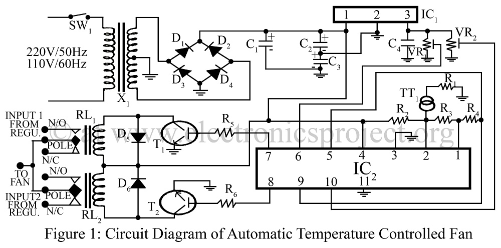
An automatic temperature-controlled fan regulates the fan speed based on temperature variations using the temperature transducer AD590 and an op-amp LM324 circuit diagram. The automatic temperature-controlled fan circuit utilizes the AD590 temperature transducer, which provides an output voltage that is...
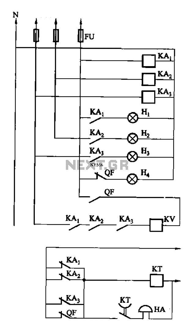
The circuit features intermediate relays KAi, KA2, and KA3, which are connected to the outlet end of the low-voltage circuit breakers. An alarm circuit is linked to a backup power supply or a battery power supply. This configuration serves...
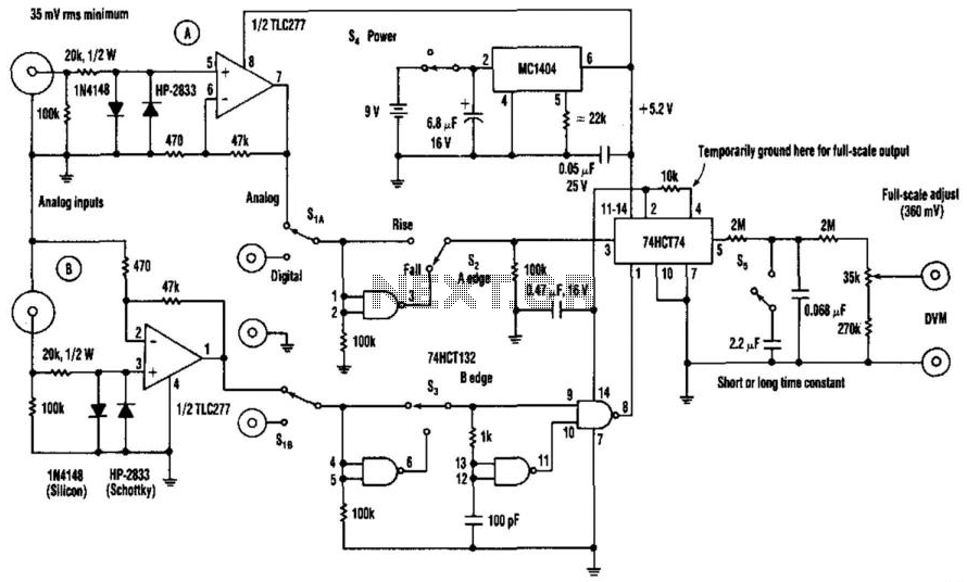
The phase-angle meter operates with both analog and digital inputs. A digital voltmeter (DVM) serves as the readout device. The output is 1 mV per degree, with a full-scale output of 360 mV corresponding to 360 degrees. The MC1404...

Function generators are essential in the design, testing, and operation of encoders, modulators, demodulators, and measurement instruments. This document presents an economical method to construct a bus-controlled sinewave oscillator that exhibits exceptionally low distortion. The circuit produces a sinusoidal...
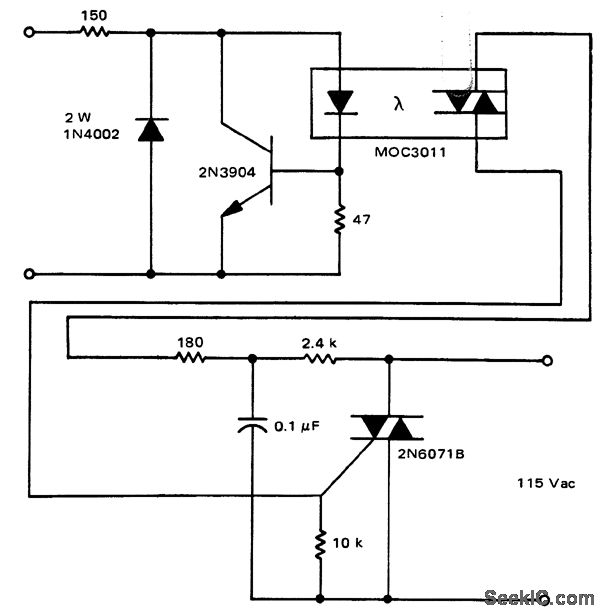
A solid-state relay circuit features an input protection mechanism utilizing the MOC3011 triac driver. The input voltage for the protection circuit can range from 3 to 30 volts DC, as noted by Motorola Semiconductor Products Inc. The solid-state relay (SSR)...
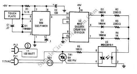
This is a three-mode lamp dimmer circuit with touch control. This circuit can be used to control a lamp in three operation modes: dim, off, and bright. It utilizes a NE555 timer. The three-mode lamp dimmer circuit designed with touch...