
LED Hat
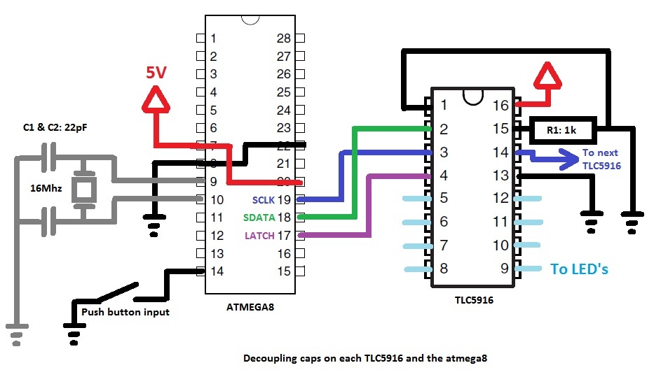
The electronic schematic for the LED hat project consists of a simple yet effective arrangement. The core component is the ATmega8 microcontroller, which serves as the brain of the operation. It is connected to eight TLC5916 LED sink drivers, each capable of controlling eight LEDs, allowing for a total of 64 LEDs. The TLC5916 chips are connected in series, where the SDO pin of one chip connects to the SDI pin of the next, creating a cascading effect for data transmission.
The power supply for the circuit must be sufficient to handle the total current drawn by all LEDs when illuminated. A suitable power source, such as a battery pack, should be chosen based on the voltage requirements of the TLC5916 and the LEDs. The circuit should include decoupling capacitors close to the power pins of the TLC5916 to ensure stable operation.
For programming the ATmega8, connections must be made to the appropriate pins for the ISP, following the ArduinoISP sketch guidelines. The programming process requires careful attention to the fuse settings, especially when using an external clock.
The animation effects are controlled through the microcontroller's firmware, which utilizes PWM to create dimming effects and smooth transitions. The implementation of 4-bit BAM allows for nuanced control over LED brightness, enhancing the visual appeal of the hat.
In conclusion, this project combines creativity and technical skill, resulting in a unique LED hat that showcases the capabilities of microcontroller programming and LED control. The circuit design is straightforward, making it accessible for enthusiasts looking to replicate or modify the project.This ridiculous hat is one of my typical procrastination projects. During swatvac for my final exams I got invited to a friends hat themed Birthday party. With nothing better to do (well apart from study for my exams) I decided that I wanted to win the best hat prize, and figured I could use up some of the spare LED`s I have laying about after my LED cube project in the process. Literally before I had even responded to the event I had started bending wire around my head to form the shape of the hat, there was no design or even consideration of how this thing was going to work but this is what I ended up with. It`s messy, it`s uncomfortable and was a complete waste of time, but It looks awesome when it`s turned on and I kicked ass in the competition.
I am not going to go into much detail here as I feel like I have spent enough time on a flashy hat, but you can find some pics, circuit diagrams and the code all here. The hat took shape fairly quickly I used thick fencing wire for the construction and routing power about my head, for all the signals I used a heap of enameled copper wire which I think actually looks pretty cool going all over the place like it is.
To drive all 64 LED`s I used 8 TLC5916 LED sink drivers, they work almost identically to the drivers in my LED cube project except they only have 8 outputs, I don`t bother with any multiplexing on the hat because I wanted to be able to do some PWM effects. The hats brain is an old atmega8 chip I had laying about and had never learned how to program until now.
The circuit diagram is fairly basic as you can see below (yes I drew it in paint, what of it), just repeat the TLC5916 part 8 times continuing the SDO -> SDI chain. To program the ATmega8 chip I used my Arduino as an ISP with the ArduinoISP sketch, follow the link for more information on how to wire it up.
I compiled and uploaded the code with AVRdude which is a terminal based program, once you get the hang of it it`s very easy to use (just get yourself a makefile to play around with). As I am using an external clock source I had to set the avr fuse bits, to make sure I didn`t make a mistake and ruin my chip which cost me an extravagant $2 I used the avr fuse calculator.
My hat uses two types of animations, the standard animations where each LED is either on or off, or dimmed animations where I use 4 bit Bit Angle Modulation (BAM) for some nice effects. My code which you can find in the downloads section is not particularly well commented but it is neat so hopefully easy enough to follow, you are welcome to ask me a question in the comments if you need a hand.
You will probably see the analogue input code in there, that is because I had a microphone input at one stage but I removed it before the party because the battery source was causing too much noise and I ran out of time trying to fix it, or something like that. 🔗 External reference
Related Circuits
When the preset is set to its maximum, the LED flashes approximately every half second. This flashing rate can be increased by using a larger capacitor value, for instance, changing from 10µF to 22µF will result in a flashing...
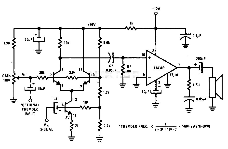
The transistors create a differential pair with an active current-source tail. This configuration, referred to as a variable-transconductance multiplier, produces an output that is proportional to the product of the two input signals. The multiplication effect arises from the...
The initial step often taken when learning about any microcontroller or embedded system is to make an LED blink. The circuit presented below illustrates the setup for interfacing an LED. Note: Due to the large dimensions of the circuit...

The VCO circuit, which has a nonlinear transfer characteristic, will operate satisfactorily up to 200 kHz. The VCO input range is effective from V% Vcc to Vcc - 2 V, with the highest control voltage producing the lowest output...

The CA3080 can be utilized as a gain-controlling device. The input signal is attenuated by resistors R1 and R2 so that a 20 mV peak-to-peak signal is applied to the input terminals. If this voltage exceeds a certain threshold,...
Every DIY enthusiast creates their own electronic dice using LEDs as indicators. This eliminates the need to physically roll dice; instead, a button is pressed. The circuit is designed to prevent any manipulation of the outcome, ensuring fairness. This...