
Authentic Looking Knight Rider Led Project

The circuit is designed to create a visual effect reminiscent of the "Knight Rider" KITT car, where the LEDs simulate the iconic chasing light pattern. The use of two 555 timers allows for precise control over the timing of the light sequences, ensuring that the intervals between the LED chases are consistent. The first timer is configured in astable mode to generate a square wave that dictates the speed of the LED chase. The second timer is set up in monostable mode to create the necessary pause between sequences by controlling the power to the 4017 decade counter.
The 4017 decade counter is responsible for driving the LEDs in a sequential manner. Each output pin of the 4017 is connected to an LED through a current-limiting resistor. When the decade counter is activated, it sequentially energizes each output pin, lighting up the corresponding LED. The addition of the OR gate IC helps to prevent unwanted interaction between the outputs, ensuring that only the intended LED lights up at any given time.
The JK flip-flop serves a dual purpose in the circuit. It not only toggles the power to the LED outputs but also adds complexity to the light sequence, allowing for the implementation of the additional light phases. Each time the decade counter completes a full cycle, the JK flip-flop changes state, resulting in an on-off pattern that enhances the dynamic effect of the light display.
This circuit can be built using common electronic components, making it accessible for hobbyists and enthusiasts. The design can be further modified to incorporate additional features, such as adjustable speed controls or different LED colors, to create a more customized light show. The overall simplicity of the circuit, combined with the potential for enhancements, makes it a versatile option for various applications, including decorative lighting and automotive displays.You see the red lights chasing up and down on the front of KIT, but in between each sequence there is a pause of about 1 second before it starts again! Almost all the other circuits I`ve come across just continually pulse a decade counter, so the leds go up and down continually.
The circuit is fairly easy and un-complicated. It uses 2 555 timers and 1 4017 Decade counter. One 555 control the flash rate for the led sequence (decade counting frequency) and the other is to turn the decade counter on and off. Once the led have gone up and down the row once (2 seconds) we switch the power to the 4017 off for 2 seconds and then back on again for another 2 seconds creating a break between each light chase. Fairly simple hey! I have not used diode on the outputs of the 4017 as I figured that the IC already has suitable protection on it`s outputs.
You could add them if you wish, just place them between the ouput and resistor to the LED. I have run mine like this continually and I can say it`s fine without. The circuit runs quite happily from 9V but could take 12V as it is, so you could mount it to say, a car! The true knight rider image! Although, I shouldn`t the police will like you though. Trent Johnson has suggested a few modifications to my original circuit. It has been suggested that a 4071B OR Gate IC is added between the outputs of the Decade counter and LEDs, to stop the decade outputs from cross talking.
Another modification is to move the 10nF capacitor that was connected to pin 15 (reset) and +V, to inbetween pin 16 and 15. This is changed to force a reset of the decade counter when the decade interupt becomes high. In some of the above pictures you can see 2 green wire leading off from the board. I put these on to just tweek my chaser speed to match the original knight rider lights! Over doing it now aren`t I. oh well. enjoy. Due to recent requests, I have designed a new version of the above circuit, that is still composed of logic circuits as it was more of a challenge to design (This could easily been done with Microcontrollers (PIC, Atmel), but not everyone has programmers).
There are quite a few more components in this version, but as you will see, it is far more versitile and robust. Well apart from the already stated facts, I have been informed that Knight Rider KITT car actually had 8 light phases, rather than the previous 6 of my early project.
This was complex to implement in Logic as the Johnson counter (4017 decade) only counts to 10, and we need 6 to pulse up and 4 back down the light chain. So the obvious answer was to use a second 4017 counter to bring the light chain back down, leaving the first 4017 to pulse the light chain up.
To keep the running light wait time "authentic", I have used a JK flip flop in a T flip flop setup to toggle on-off and off-on every time the counting reaches one cycle. So it`s on for one up-down cycle, off for the second up-down cycle and back on for the third up-down cycle and so on.
The JK toggles the power and so the output from the OR gates to the LEDs. 🔗 External reference
Related Circuits
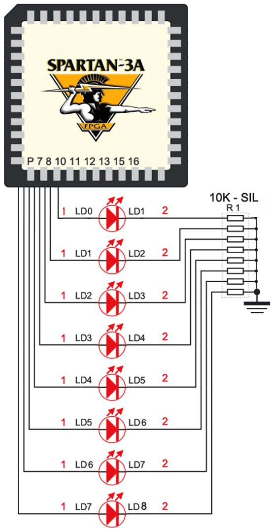
The Spartan-3an board features eight LEDs connected to FPGA I/O pins. The cathode of each LED is connected to ground through a 330-ohm resistor. To illuminate a specific LED, the corresponding FPGA control signal must be set to High. The...
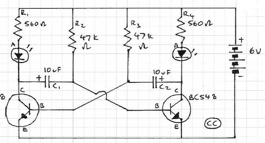
Blinks 2 LEDs in sequence. An explanation of its operation is requested. It is understood that a capacitor charges, causing the LED to turn off, and when it discharges, the LED turns on. However, clarification on the purpose of...
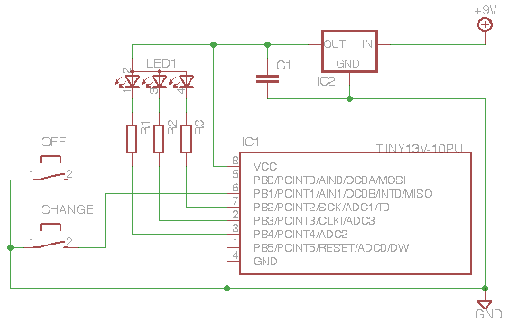
This project demonstrates the use of an ATTiny microcontroller and an RGB LED to create a light that continuously cycles through random colors, with the ability to change color dramatically at the press of a switch. The inspiration for...
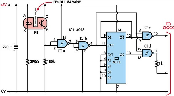
This document outlines the construction of a pendulum-controlled clock designed for high accuracy. Although it has a retro appeal, it represents an intriguing project. The project requires a spare quartz clock, which must be modified by isolating two pads...
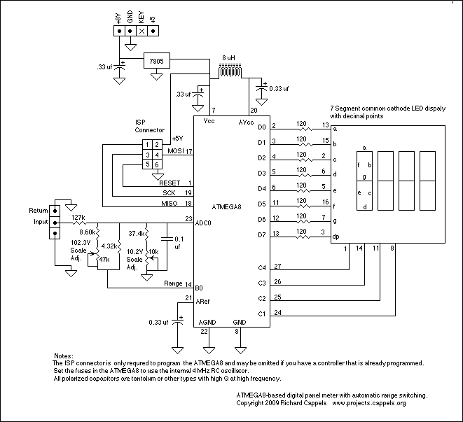
To explain in a little more detail, using the ATMEGA8's internal 2.5 volt band gap reference means that by using a resistive divider ahead of the A-to-D converter, the input could be scaled such that any voltage range from...
The circuit diagram depicted in Figure 5 illustrates a system for charging a lead-acid battery using 220V AC power. The circuit employs a capacitor, buck converter, and diode rectifier for this purpose. A red LED indicates the charging status....