
LED SignBoard with PIC 16F84A
In the figure, it can be seen that the LEDs light up every time, with the combination of the column gate RA and columns of the door of RB PIC16F84A. Note that the length of each lighting column with LEDs is 1/16. If an external circuit with registers holds data for each combination, the time of LED lighting can grow. However, this circuit does not utilize that feature.
Note that in each LED anode, there is a current-limiting resistor, which is necessary to protect the LEDs and the pins of the door RB from damage.
For timing, the processor uses a ceramic filter (resonator) or a 10MHz crystal along with two 22pF ceramic capacitors.
The voltage stabilization circuit (IC2) reduces the voltage from 12VDC to 5VDC, with capacitors used to smooth and filter the output. When all eight LEDs are lit simultaneously, the circuit's consumption reaches about 90 mA. A voltage regulator rated for 100 mA can be used for safety, but a 1 Ampere (1A) regulator is recommended for added security.
This circuit is designed to control an array of LEDs using a microcontroller (PIC16F84A) and a 4-to-16 line decoder (74HC154). The output pins from the microcontroller (RA0-RA3) select which column of LEDs to activate, while the pins (RB0-RB7) determine the specific LEDs within that column to illuminate based on their logic states. The use of transistors allows for driving higher currents through the LEDs while isolating the microcontroller from the load. The current-limiting resistors prevent excessive current from flowing through the LEDs, ensuring their longevity and preventing damage to the microcontroller's output pins. The timing circuit ensures accurate operation of the microcontroller, while the voltage regulation circuit provides stable power for reliable performance.The pins RA3 to RA0, are used as outputs driving each column LED. The pins RB0 to RB7 are used as outputs driving signal for each column LED. The 74HC154 (Decoder 4 to 16) is the chip that decodes the signal into a binary digit dekaexapsifio. In the left figure all the pins of the door at a reasonable RA 0 (Low), in which case only the output 0 of the 74HC154 decoder is logical 0 and the others at logic 1. Therefore only the transistor TR1 conducts and powered on the column of Led connected with it. For what Led by this column will turn determined by the logic state will find the pins RB7-RB0 door RB.
For example, the left shape, because the pins RB0 and RB4 are logical 0 (Low), the Led D1 and D5 will illuminate. The remaining Led the column is connected to pins of door RB will remain extinguished. Also will remain switched off and the remaining Led columns because the transistors that supply them with power do not lead me. In the figure you can see the Led light up every time, with the combination of the column gate RA, and columns of the door of RB PIC16F84A.
Note that the length of each lighting column with Led is 1 / 16. If you use an external circuit with registers hold data for each combination, the time of Led Lighting can grow. But the circuit will increase to one in our example is not used. Note that in each anode Led a resistance limiting current, which is necessary because the Led and protects the feet of the door RB from the disaster.
Timing Circuit For the timing of the processor used a ceramic filter (Resonator) or 10MHz crystal and two 22pF ceramic capacitors Feeder circuit The IC2 stabilize the voltage from 12VDC to 5VDC and capacitors to smooth and filter. If all eight LEDs light up simultaneously, the consumption of the circuit reaches about 90 mA. Stabilizer of the order of 100 mA can be used for security, but use a rate of one Ampere (1A). 🔗 External reference
Related Circuits
This is a variable power supply controlled by a PIC microcontroller. An LCD display is included in the circuit to show the actual output voltage and current values. A push-button switch is used to adjust the output voltage and...
Its based on inductive pickup and very easy to install. Have a look at the pic. (remove LED and connect transistor collector to pin4). I hope it will exactly suits to your tachometer. More: I found your PIC project...
In conventional white LED design, the Max1916 low-dropout bias supply for white LEDs serves as a high-performance alternative to simple ballast resistors. The Max1916 is an integrated circuit designed to provide a stable and efficient bias supply for white LEDs....
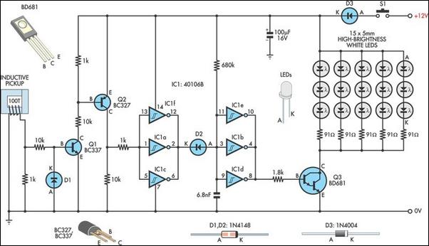
A timing strobe can be constructed using high-brightness LEDs and a few common components. Ignition pulses from the number one cylinder high-tension lead are used to trigger the circuit via a homemade inductive pickup. Transistors Q1 and Q2 buffer...
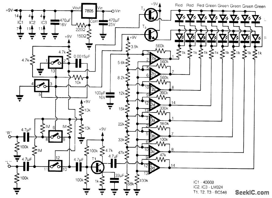
This circuit offers a cost-effective alternative to the LM3915 series LED displays. It utilizes a square-wave oscillator constructed with two CMOS analog switches, which alternately select the right and left channels for monitoring and display. The chosen signal is...
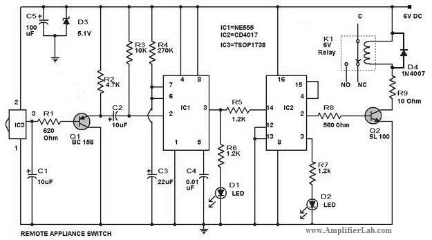
The circuit diagram of a remote-controlled appliance switch circuit includes two main components: IC1 (NE 555) and IC2 (CD 4017). The remote-controlled appliance switch circuit is designed to allow users to control electrical appliances wirelessly. The heart of this circuit...