
led table reading lamp circuit
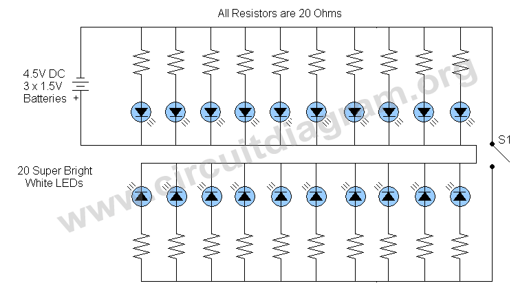
The LED lamp circuit features a versatile design, making it suitable for multiple lighting scenarios. The use of 20 super bright white LEDs ensures high luminosity, providing adequate illumination for reading or working in dim environments. Each LED is paired with a 20 Ohm current limiting resistor, which is essential for preventing excessive current from flowing through the LEDs, thus prolonging their lifespan and maintaining consistent brightness.
The inclusion of switch S1 allows for flexibility in light output. By disconnecting half of the LEDs, users can achieve a lower light level, which is particularly advantageous for tasks that require minimal lighting or when conserving battery life is a priority. This feature enhances the circuit's efficiency, making it suitable for extended use in portable applications.
Powering the circuit with three 1.5-volt batteries (totaling 4.5 volts) provides a reliable energy source. The battery configuration ensures that the circuit can operate effectively without the need for an external power supply, making it ideal for emergency situations or outdoor activities. The design can be easily adapted for different battery types, allowing for customization based on availability and user preferences.
Overall, this LED table lamp circuit is a practical solution for various lighting needs, combining functionality, efficiency, and portability in a single design. The careful selection of components and thoughtful circuit design contribute to its effectiveness as a versatile lighting tool.This Led table or reading lamp circuit can be used for many purposes for example as a reading lamp for bed, desktop or table lamp, keyboard lamp (to view keys of your computer keyboard in dim light), as an LED emergency light in the absence of AC supply, as a portable light etc. This led lamp circuit is consist of 20 super bright white LEDs, each LED is using a separate current limiting resistor of 20 Ohms. The switch S1 is used to disconnect the 10 LEDs from the supply, it can be useful when you want low light and also save power from the batteries. The circuit can be operated with 3 x 1. 5 volt batteries. 🔗 External reference
Related Circuits
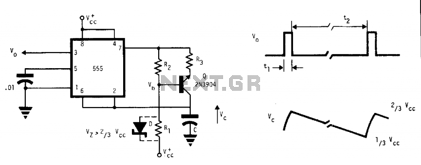
This free-running multivibrator utilizes an external current sink to discharge the timing capacitor, C. As a result, the interval can easily be 1000 times the pulse duration, t1, which defines a positive output. The voltage across the capacitor, V,...
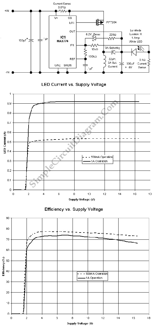
This is a high-power LED driver circuit designed to accommodate a wide input-voltage range. The circuit utilizes a buck/boost converter controller to regulate the current supplied to a white LED. The high-power LED driver circuit is engineered to effectively manage...
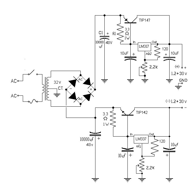
The 10A variable power supply circuit is symmetrical and can provide a symmetrical output voltage ranging from ±1.2 volts to ±30 volts DC, with a maximum current of 10A. This circuit utilizes symmetrical variable voltage regulators LM317 and LM337,...
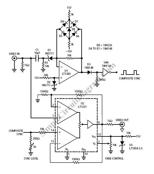
Fading a video signal cannot be achieved merely by attenuating the composite signal, as the synchronization signal may fall below an unacceptable level. Fading a video signal involves a careful adjustment of both the luminance and chrominance components while...

The circuit depicted in Figure 3-190 includes an armature circuit with two startup resistors, Ri and Rz, connected in series through the main switch SA to facilitate starting, stopping, and speed control. During the startup phase, two relays, KTi...
This is a power-on time delay relay circuit that utilizes the emitter/base breakdown voltage of a standard bipolar transistor. The reverse-connected emitter/base junction of a 2N3904 transistor functions as an 8-volt zener diode, establishing a higher turn-on voltage for...