
555 Astable oscillator
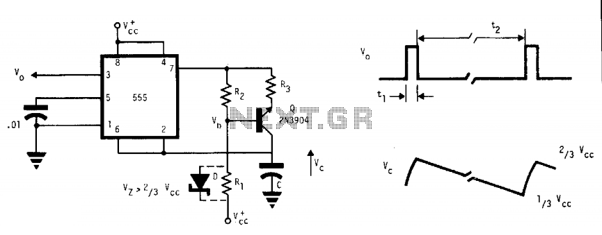
This circuit functions by generating a continuous square wave output, where the timing capacitor C is charged and discharged in a cycle determined by the external current sink. The duty cycle of the output is inherently low due to the nature of the timing mechanism. The external current sink plays a crucial role in controlling the discharge rate of the capacitor, which in turn influences the pulse duration and frequency of the output signal.
In operation, when the timing capacitor C charges, it reaches a threshold voltage that triggers the output to go high. During this period, the voltage V across the capacitor rises exponentially. Once the external current sink is activated, it discharges the capacitor, causing the voltage to drop rapidly, resulting in a negative-going ramp. The timing of this cycle can be adjusted by changing the values of the capacitor and the resistive components associated with the current sink.
The design of this multivibrator is particularly useful in applications where precise timing intervals are critical, such as in clock generation for digital circuits or in timing applications where low duty cycles are acceptable. The ability to achieve a wide range of pulse durations by manipulating the external components allows for versatility in various electronic applications.This free-running multivibrator uses an external current sink to discharge the timing capacitor, C. Therefore, interval ^ may easily be 1000 the pulse duration, t1( which defines a positive output. Capacitor voltage, V^, is a negative going ramp with exponential rise during the pulse output periods. This as is has low duty cycle. 🔗 External reference
Related Circuits
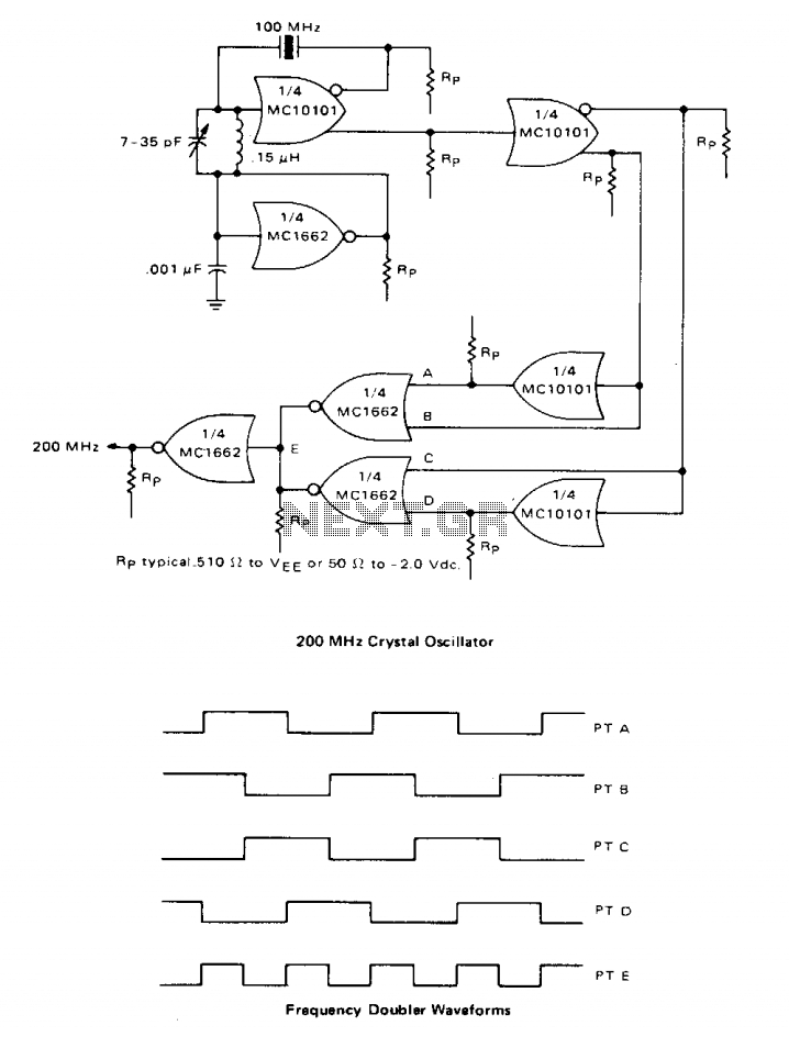
A high-speed oscillator can be created by integrating an MECL 10 crystal oscillator with an MECL III frequency doubler. One section of the MC10101 is configured as a 100 MHz crystal oscillator, with the crystal placed in series within...
This circuit was designed to drive an impact counter, utilizing the ICL8038 as its core component. It is intended for a motor that operates a conveyor, with the motor featuring a feedback system known as a tachogenerator. Only a...
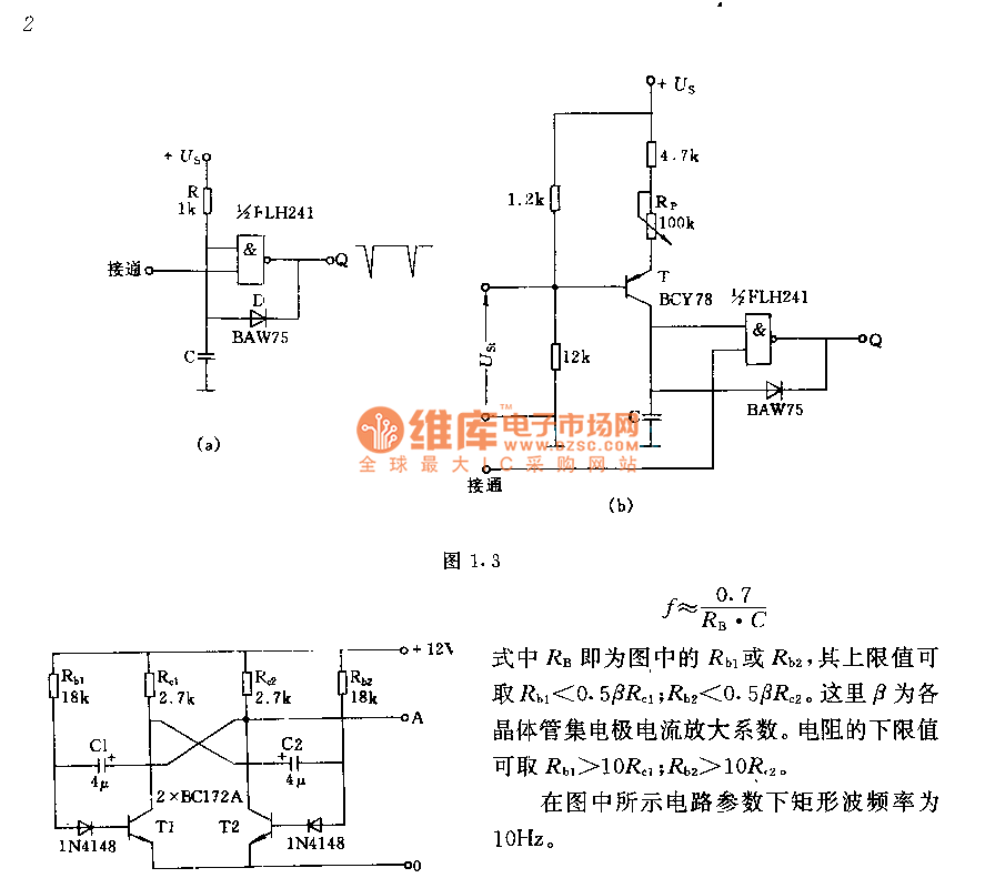
The circuit consists of two components whose parameters and models are designed to simultaneously generate a rectangular wave with a duty cycle of 1:1. The frequency is defined by the equation f = 0.7/(RB * C), where RB refers...
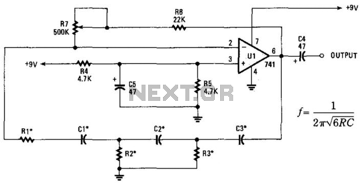
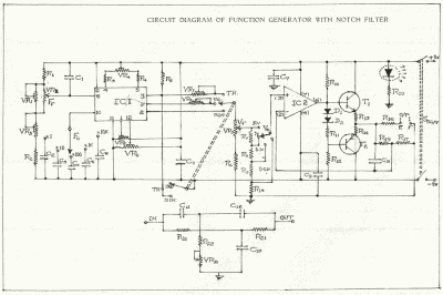
This phase-shift oscillator is suitable for audio oscillator applications. Adjust R7 to achieve a good sine wave. An amplifier gain of 29 is necessary for oscillation. If C=C1=C2=C3 and R=R1=R2=R3: Typically, R will range from 1 to 100 kOhm...
This circuit is basically simple and easy to build, it uses two transistors as active components and a few passive components like resistors, capacitors and two LEDs. The circuit makes use of the MPS2222 transistor. You can use any...
This is a basic 555 square wave oscillator used to produce a 1 kHz tone from an 8-ohm speaker. In the circuit on the left, the speaker is isolated from the oscillator by an NPN medium power transistor, which...
Warning: include(partials/cookie-banner.php): Failed to open stream: Permission denied in /var/www/html/nextgr/view-circuit.php on line 713
Warning: include(): Failed opening 'partials/cookie-banner.php' for inclusion (include_path='.:/usr/share/php') in /var/www/html/nextgr/view-circuit.php on line 713