
LED Torch Uses Blocking Oscillator
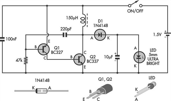
The circuit utilizes a two-transistor configuration to create a blocking oscillator, which is a type of oscillator that generates a square wave output. This output is used to drive an LED, providing illumination. The oscillator's design allows it to operate efficiently with a low input voltage, making it suitable for battery-powered applications.
In this configuration, one transistor acts as a switch, while the other serves as a feedback element. When the circuit is powered on, the initial current through the first transistor causes it to turn on, allowing current to flow through the second transistor. This feedback loop continues until the energy stored in the circuit's inductor is released, generating a high voltage pulse that powers the LED.
The inherent current limit of the circuit is crucial for preventing damage to the components. By carefully selecting the resistor values and the characteristics of the transistors, the circuit ensures that the current remains within safe limits while still providing adequate brightness from the LED.
Additional components may include a small inductor, which is essential for energy storage and voltage stepping, as well as capacitors to stabilize the circuit and filter out any noise. The overall design is compact and efficient, making it ideal for portable lighting solutions. The simplicity of the circuit allows for easy assembly and troubleshooting, making it accessible for both beginners and experienced electronics enthusiasts.This simple LED torch is driven by a 2-transistor blocking oscillator which steps up the voltage from a 1.5V cell. It relies on the inherent current limit.. 🔗 External reference
Related Circuits
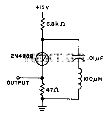
The capacitor charges until the switching voltage is reached. When the switch (SUS) is activated, the inductor causes the current to oscillate. When the current through the switch drops below the holding current, the device turns off, and the...
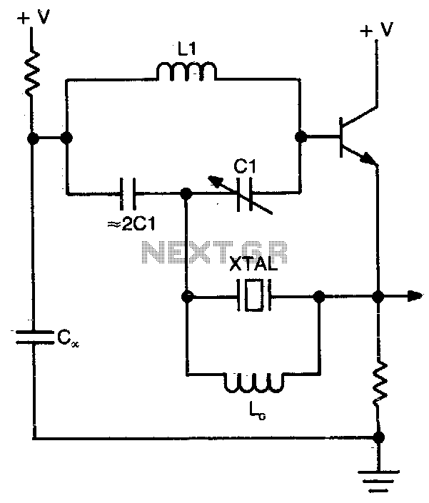
This circuit operates at or near series resonance. It is a well-designed circuit with no parasitics. It is easy to tune and has good frequency stability. The circuit in question utilizes series resonance to achieve optimal performance. At series resonance,...
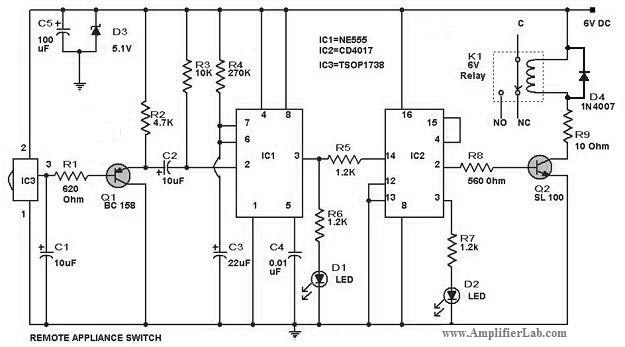
The circuit diagram of a remote-controlled appliance switch circuit includes two main components: IC1 (NE 555) and IC2 (CD 4017). The remote-controlled appliance switch circuit is designed to allow users to control electrical appliances wirelessly. The heart of this circuit...
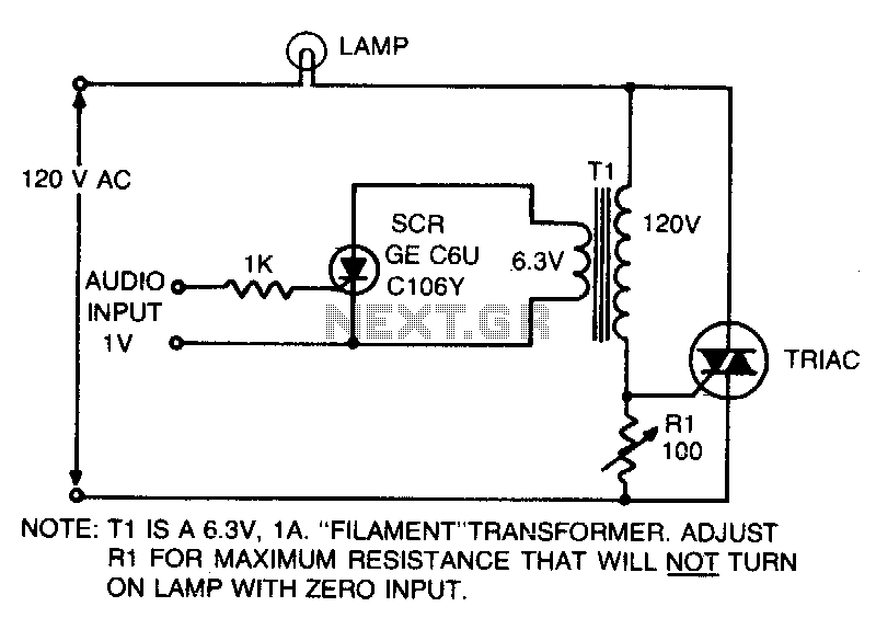
This is an on-off control with an isolated, low voltage input. The switching action occurs rapidly compared to the response time of the lamp and the human eye, resulting in an effect with audio input that resembles a proportional...
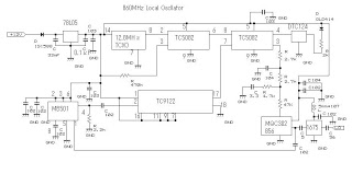
This 860 MHz Phase Locked Loop (PLL) oscillator circuit is designed for a 1200 MHz transverter's local oscillator with 435 MHz rigs. The oscillator circuit utilizes Toshiba PLL synthesizer ICs. The TC9122P is a user-friendly preset counter for determining...

This is a simple circuit where an LED turns on only after a predetermined time once the power supply is activated. Initially, when the power supply is turned on, the transistor remains off. The capacitor charges through the preset...
Warning: include(partials/cookie-banner.php): Failed to open stream: Permission denied in /var/www/html/nextgr/view-circuit.php on line 713
Warning: include(): Failed opening 'partials/cookie-banner.php' for inclusion (include_path='.:/usr/share/php') in /var/www/html/nextgr/view-circuit.php on line 713