
Use an LED Matrix Horizontally
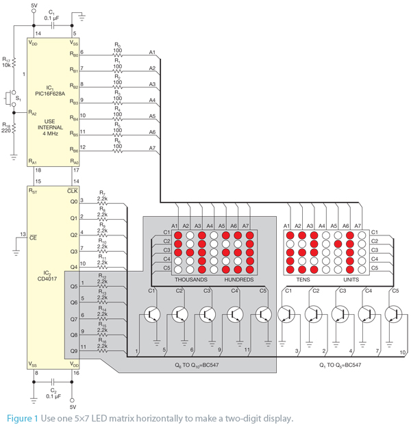
The seven-segment LED display is a widely used electronic component for visual representation of numerical information. It consists of seven individual light-emitting diodes (LEDs) arranged in a figure-eight pattern. Each segment can be illuminated in various combinations to represent the digits 0 through 9, as well as some alphabetic characters and symbols. The segments are typically labeled from 'a' to 'g', with an optional eighth segment for the decimal point.
In a typical application, the display is controlled by a microcontroller or a dedicated driver IC that can send signals to each segment. The microcontroller outputs binary signals corresponding to the desired digit, which are then translated by the driver to activate the appropriate segments. This allows for efficient and dynamic display of numerical data, making it ideal for use in clocks, calculators, and various electronic devices.
The schematic for a seven-segment display circuit generally includes the display itself, a microcontroller or logic circuit for control, and current-limiting resistors for each segment to prevent excessive current flow which could damage the LEDs. The microcontroller can be programmed to cycle through different numbers, allowing for real-time updates of the displayed information.
In summary, the seven-segment LED display serves as a fundamental component in electronic devices, providing a clear and effective means of conveying numerical information through simple visual signals.LEDs provide a convenient way to electronically display information. Although the seven-segment LED display, arranged in the form of the digit 8, is commo.. 🔗 External reference
Related Circuits

The main oscillator is printed in blue and is voltage controlled. In this construction, the VCO range is 88 to 108 MHz. As you can see from the blue arrows, some energy goes to an amplifier and some energy...
A circuit of measurement of level based on a typical application of National. The circuit round the IC1 makes input adaptation and amplification with the trimmer TR1 [GAIN]. The circuit round the IC2 makes half-wave rectification of acoustic signal....
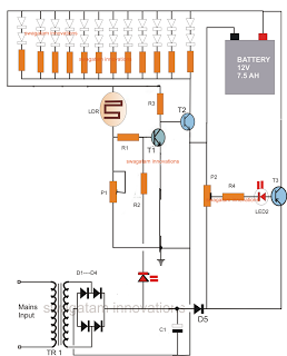
The following circuit is an LED emergency light circuit featuring advanced functionalities such as overcharge battery cut-off, daytime auto-disable, and automatic activation of the LEDs during AC mains failure, reverting to charging mode when power is restored. The circuit...
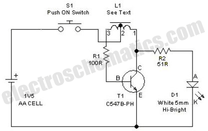
This simple LED driver circuit allows the operation of up to seven LEDs using a single NiMH (Nickel Metal Hydride) AA cell. The circuit generates voltage pulses. The LED driver circuit is designed to efficiently power multiple LEDs while maintaining...
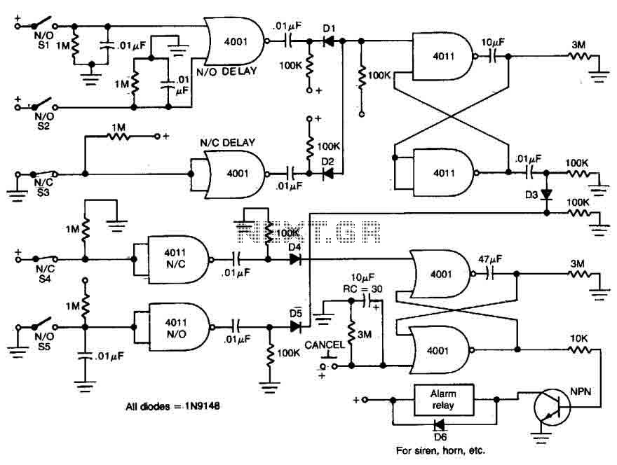
This circuit features open and closed loop contacts (switches 1, 2, 3) that activate the alarm, which remains on for a duration of 5 to 10 minutes. The triggering delay for entrance and exit is set to 27 seconds....

This colorful backlit aquarium light provides a natural appearance to the aquarium tank. The aquarium LED lighting circuit automatically turns on at sunset. The aquarium LED lighting system enhances the aesthetic appeal of the aquarium by simulating natural lighting conditions....