
LED Ultraviolet exposure box
On the bottom board I have added red LEDs. These LEDs help me align the top and bottom films. I have used low brightness, cheap, matte LEDs as I have to look into them when aligning the films. Connection is similar, 3 LEDs in series with a 220Ω resistor, except for the last row which contains 2 LEDs and a 330Ω resistor. These are not really necessary, aligning the films can be done in a dim ambient light.
For safety reasons and extra functionality I added a switch to turn off the UV light when the box opens, turn on the red light and stop the timer. This makes the box more high tech and gives it a professional behavior.
LED spacing
I used nuts glued on the interior walls of the box to hold the bottom 4 mm thick plexiglass panel. The choice was simply of what was easily available: nuts. Don't use normal glass as it blocks ultraviolet light. There is no top panel mounted, because it is part of the aligning procedure: I put the first film on the bottom, then the board and the second film is taped to a smaller piece of plexiglass. Aligning means aligning the smaller piece of the plexiglass so that the two layers overlap perfectly. Having the film attached to it makes it easier. Extra markings outside the board help this (ghost vias). Part two should contain a more detailed tutorial on making double-sided boards.
The final assembly allows an area of about 10x15cm of board size, with the interior dimensions of the box being 18cm long, 11cm wide and 5.5cm deep for each of the two halves. Exterior dimensions will depend on the thickness of the material used. Each board contains 7×12 UV LEDs, with 3 and respectively 4 holes between them (the actual spacing between the center of the LEDs is the same). The distance between the top of the LEDs and the board is 3.5cm, including the 4mm plexiglass panel. Check out the detail below to see the LED arrangement on a normal 0.1" or 1.27 spaced board:
What you can see in the picture above, from 2 to 7 minutes exposure if perfect. At 7 minutes some overexposure starts to show up, only in large copper areas, due to the fact that the film was printed with a laser printer. This result is very different from what I have obtained when using a fluorescent tube: below 12 minutes it was clearly underexposed and above 14 it was clearly overexposed, leaving only a small interval where it was right.
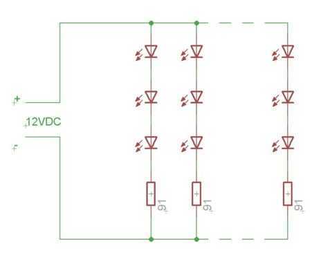
So far I have made 4 boards with 2 minute exposure and they came out perfect. When free time will be available I will investigate what the results are for less than 2 minute exposure. As any time between 2 and 7 minutes seems to work, there is no immediate need for a timer. Still, part two should contain a basic circuit for this. The schematic shows, symbolically, the red and UV LED arrays through the basic cell that is repeated on the panels: a series of three LEDs and a resistor. As you can see, there is no way to turn on the UV light when the lid is open, even if such a command would come from the microcontroller. The microcontroller can turn the UV light on via the MOS transistor only when the lid is closed. This is controlled through software too. In order to sense whether the lid is open or not, the microcontroller monitors the state of the cathode of the red LED array. When the lid is open, this is shorted to ground and the micro sees a low logic level. When the lid is open the red LEDs will conduct current and force the microcontroller to see a high. This current is small, limited by the 10K resistor and therefore the LEDs do not appear to be on. I could have chosen to leave the red LEDs on all the time as this does not influence the functionality of the exposure box, but it adds extra consumption and more heat needs to be dissipated by the lower panel.
Although it is not totally justified, I decided to go the full effort and make this timer with a display. There could be many more ways to do this starting from a simple 555 circuit. I wanted the circuit to be a challenge for the box itself, so small SMD parts are used wherever possible.
The display is a KW4-361ASB from Luckylight. It is small, 9mm digit height and has 4 multiplexed digits. There were two basic criteria for selecting this particular part, first I wanted it to be small and efficient so that a small current is enough for a bright display and second I wanted it to be multiplexed as this simplifies board layout.
I choose an ATTiny2313 microcontroller as it has all the features needed to implement all the tasks: sufficient pin driving capability, a timer, enough pins and memory. It's got an internal oscillator too, but as I missed it, the tolerance is within 10% which I consider too high for this project. I have later added a crystal on the board but adjusted the starting timer value on my particular circuit to compensate for the internal oscillator deviance. This was easy as I knew that the refresh frequency for the display should be 50Hz, so a frequency meter was all that I needed. I believe that this should not fluctuate and no future compensation will be needed to maintain the error at a small value, maybe less than 2-3%. I do suggest using a quartz crystal, but this is not mandatory, you may use my method or simply accept the maximum 10% tolerance.
The circuit design consists of a series of interconnected components that enable the operation of the UV exposure box. The primary elements include the OSSV53E1A LEDs arranged in a configuration that provides optimal UV exposure for PCB photolithography. The LEDs are connected in series, with appropriate resistors to limit current and ensure consistent operation. The use of the LM317 voltage regulator allows for stable voltage supply, which is crucial given the non-linear characteristics of the LEDs.
The red LEDs serve a dual purpose of alignment assistance and safety indication. Their connection is similar to that of the UV LEDs, with different resistor values to achieve the desired brightness. The inclusion of a switch to control the UV light enhances safety by preventing exposure during maintenance or film alignment.
The microcontroller, an ATTiny2313, orchestrates the entire operation, controlling the timing of exposure, monitoring the status of the lid, and managing the display. The display provides a user-friendly interface for setting and monitoring exposure times. The circuit is designed to be compact, utilizing SMD components to save space and improve thermal management.
Overall, the schematic represents a well-thought-out design that balances functionality, safety, and ease of use, allowing for efficient PCB exposure and alignment processes.The LEDs are OSSV53E1A from OptoSupply and they have an 140° angle. This means that the first plane with uniform density can be obtained at a shorter distance from the LED, for a given spacing between LEDs which means smaller height for the board. Their peak wavelength is 405nm, which is higher than recommended by the boards' manufacturer. Results showed they emit sufficient UV light in the responsive spectrum of the photo resist to allow for a perfect exposure.
I wanted to use a common voltage so 3 LEDs in series with a 91? resistor are connected to 12V to ensure a 20mA current. The final setup will contain a LM317 for stabilizing as I don't plan on using my variable regulated supply all the time. There is another reason for this, due to the non linear nature of the LEDs, varying 12V with +/-5% creates much larger current variations which influences the required time.
Putting a regulator on the box simply allows more flexibility in choosing the power supply. On the bottom board I have added red LEDs. These LEDs help me align the top and bottom films. I have used low brightness, cheap, matte LEDs as I have to look into them when aligning the films. Connection is similar, 3 LEDs in series with a 220? resistor, except for the last row which contains 2 LEDs and a 330? resistor. These are not really necessary, aligning the films can be done in a dim ambient light. For safety reasons and extra functionality I added a switch to turn off the UV light when the box opens, turn on the red light and stop the timer. This makes the box more high tech and gives it a professional behavior. LED spacing I used nuts glued on the interior walls of the box to hold the bottom 4 mm thick plexiglas panel.
The choice was simply of what was easily available: nuts. Don't use normal glass as it blocks ultraviolet light. There is no top panel mounted, because it is part of the aligning procedure: I put the first film on the bottom, then the board and the second film is taped to a smaller piece of plexiglas. Aligning means aligning the smaller piece of the plexiglas so that the two layers overlap perfectly. Having the film attached to it makes it easier. Extra markings outside the board help this (ghost vias). Part two should contain a more detailed tutorial on making double sided boards. The final assembly allows an area of about 10x15cm of board size, with the interior dimensions of the box being 18cm long, 11cm wide and 5.5cm deep for each of the two halves.
Exterior dimensions will depend on the thickness of the material used. Each board contains 7×12 UV LEDs, with 3 and respectively 4 holes between them( the actual spacing between the center of the LEDs is the same). The distance between the top of the LEDs and the board is 3.5cm, including the 4mm plexiglas panel. Check out the detail below to see the LED arrangement on a normal 0.1? or 1.27 spaced board: What you can see in the picture above, from 2 to 7 minutes exposure if perfect.
At 7 minutes some over exposure starts to show up, only in large copper areas, due to the fact that the film was printed with a laser printer. This result is very different from what I have obtained when using a fluorescent tube: below 12 minutes it was clearly underexposed and above 14 it was clearly overexposed, leaving only a small interval where it was right.
So far I have made 4 boards with 2 minute exposure and they came out perfect. When free time will be available I will investigate what the results are for less than 2 minute exposure. As any time between 2 and 7 minutes seems to work, there is no immediate need for a timer. Still, part two should contain a basic circuit for this. The schematic shows, symbolically, the red and UV LED arrays through the basic cell that is repeated on the panels: a series of three LEDs and a resistor.
As you can see, there is no way to turn on the UV light when the lid is open, even if such a command would come from the microcontroller. The microcontroller can turn the UV light on via the MOS transistor only when the lid is closed. This is controlled through software too. In order to sense whether the lid is open or not, the microcontroller monitors the state of the cathode of the red LED array.
When the lid is open, this is shorted to ground and the micro sees a low logic level. When the lid is open the red LEDs will conduct current and force the microcontroller to see a high. This current is small, limited by the 10K resistor and therefore the LEDs do not appear to be on. I could have chosen to leave the red LEDs on all the time as this does not influence the functionality of the exposure box, but it adds extra consumption and more heat needs to be dissipated by the lower panel. Although it is not totally justified, I decided to go the full effort and make this timer with a display.
There could be many more ways to do this starting from a simple 555 circuit. I wanted the circuit to be a challenge for the box itself, so small SMD parts are used wherever possible. The display is a KW4-361ASB from Luckylight. It is small, 9mm digit height and has 4 multiplexed digits. There were two basic criteria for selecting this particular part, first I wanted it to be small and efficient so that a small current is enough for a bright display and second I wanted it to be multiplexed as this simplifies board layout.
I choose an ATTiny2313 microcontroller as it has all the features needed to implement all the tasks: sufficient pin driving capability, a timer, enough pins and memory. It's got an internal oscillator too, but as I missed it, the tolerance is within 10% which I consider too high for this project.
I have later added a crystal on the board but adjusted the starting timer value on my particular circuit to compensate for the internal oscillator deviance. This was easy as I knew that the refresh frequency for the display should be 50Hz, so a frequency meter was all that I needed.
I believe that this should not fluctuate and no future compensation will be needed to maintain the error at a small value, maybe less than 2-3%. I do suggest using a quartz crystal, but this is not mandatory, you may use my method or simply accept the maximum 10% tolerance.
🔗 External reference
Related Circuits
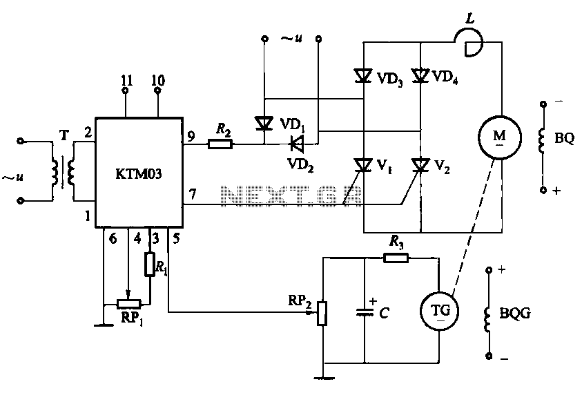
The adjustment potentiometer for the Raspberry Pi can modify the conduction angle of the thyristor VI and V2, which in turn adjusts the speed of the DC motor M. The speed feedback circuit is implemented using a tachometer generator...
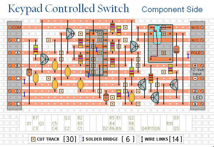
This is a universal version of the four-digit alarm control keypad. The design has been modified to free up the relay contacts, enabling the circuit to function as a general-purpose switch. A single pole changeover (SPCO) or single pole...
The circuit was designed to work with an audio power amplifier which operated off +18v-0v-18v power rails. The actual voltage used is not too critical except that the feedback is referred to the LED chain which itself is anchored...
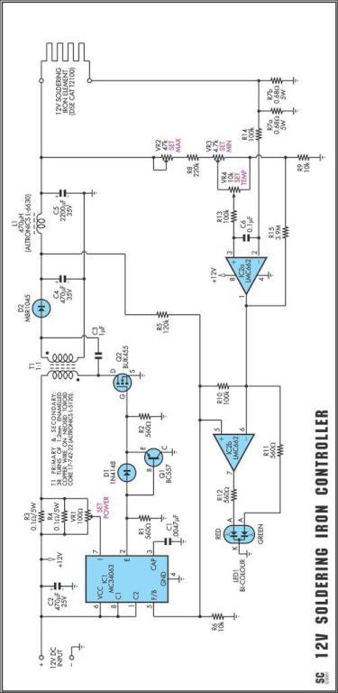
One reason why commercial soldering stations are expensive is that they typically require soldering irons with built-in temperature sensors. Commercial soldering stations are designed to provide precise temperature control and consistency during soldering operations, which is essential for achieving reliable...
A tiny sandwich flag connected perpendicular to the motor spindle aids observation of how long it takes to complete one full rotation. This worked initially, as each burst from the capacitor barely moved the flag 1/4 of a rotation....

This LED VU Meter (volume unit) is designed to monitor and display power levels present at the speaker terminals of a stereo audio power amplifier. The levels are represented in ten discrete steps using ten LEDs for each channel,...