
LED VU Meter by LM339 PCB
The circuit employs LM339 voltage comparators, which are designed to compare two input voltages and output a high or low signal based on the comparison. In this application, the comparators are used to monitor the input signal corresponding to audio power levels. The voltage divider is critical for establishing reference voltages for each comparator, effectively setting thresholds that determine when each LED will light up.
The first comparator is connected to a reference voltage derived from the voltage divider, calibrated to activate the first LED at the desired input level. Subsequent comparators are similarly connected, with their reference voltages set higher, ensuring that each LED lights up at progressively higher input levels. This arrangement allows for a visual representation of audio power levels, providing users with an intuitive way to gauge volume.
The circuit's design can be enhanced with additional features such as an adjustable sensitivity control, which could involve a potentiometer in the input stage. This would allow users to fine-tune the circuit's response to different audio sources or environments.
Power supply considerations for the LM339 include ensuring that the voltage supplied meets the operational requirements of the comparators while providing adequate current to drive the LEDs. Additionally, current-limiting resistors should be included in series with the LEDs to prevent damage from excessive current.
In summary, this circuit serves as a useful tool for monitoring audio power levels through a visual display of LEDs, utilizing the LM339 comparators and a voltage divider to create a responsive and informative volume level indicator.The circuit below uses two quad voltage comparators (LM339) to illuminate a series of 8 LEDs indicating volume level. Each of the 8 comparators is biased at increasing voltages set by the voltage divider so that the lower right LED comes on first when the input is about 400 millivolts or about 22 milliwatts peak in an 8 ohm system.
The divider vol tages are set so that each LED represents about twice the power level as the one before so the scale extends from 22 milliwatts to about 2. 5 watts when all LEDs are lit. The sensitivity can be decreased with the input control to read higher levels. I have not built or tested this circuit, so please let me know if you have problems getting it working.
The power levels should be as follows: 🔗 External reference
Related Circuits
This circuit utilizes the TLC555CP timer integrated circuit to flash an LED approximately twice per second. This specific 555 timer operates on a voltage of only 3 volts, allowing it to be powered by two 1.5-volt cells. When using...
This project explains a very powerful frequency counter which has many useful software functions. The software can add or subtract 3 different IF frequencies (±455 kHz, ±10.7 MHz, and ±21.4 MHz). You have also two levels of resolutions, 1...
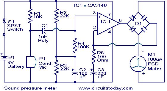
This circuit is a simple sound level checker, useful for setting up home theater systems by testing sound pressure levels across different channels and positions in a room. The design features a non-inverting amplifier utilizing the CA 3140 operational...

Most LED driver circuits utilize a series resistor to regulate the current flowing through the LED. This method is optimal for applications that require only a few LEDs. However, for applications involving many LEDs, this approach becomes inefficient, leading...
The IC1 is a 555 timer IC connected for astable operation. The clock pulses are fed to the IC2 via the 10K resistor. The IC2 is a 10-stage counter; output 6 (pin 5) is connected to RESET (pin 15),...
The circuit presented is designed to prevent burning one's tongue by monitoring the temperature of coffee. It consists of a voltage regulator, a temperature-to-voltage converter, a comparator, and two LEDs. In general, the circuit operates as follows: if the...