
led workbench lighting

The workbench lighting unit is designed to be compact and efficient, making it ideal for hobbyists who require portable illumination for detailed electronic projects. The use of the LM317L voltage regulator allows for adjustable output voltage, which is crucial for ensuring that the LED operates within its specified ratings, thus prolonging its lifespan and maintaining brightness. The choice of a 5mm white LED is significant due to its high luminous efficacy, providing ample light for inspection tasks without generating excessive heat.
The input power source is versatile, accommodating a range of 9 to 18 volts, which allows for flexibility depending on the available power supply. The current rating of 100 mA is sufficient for driving the LED while also providing headroom for additional components if necessary. The inclusion of the 51 Ohm resistor (R3) is essential for limiting the current flowing through the LED, protecting it from potential overcurrent conditions that could lead to failure.
The use of the 1N4001 diode (D1) ensures that the circuit is safeguarded against reverse polarity connections, which can occur if the power supply is connected incorrectly. This feature is particularly important in portable applications where users may frequently connect and disconnect the power supply.
Electrolytic capacitors C1 and C2 are used to filter any voltage spikes or noise from the power supply, ensuring that the voltage regulator operates smoothly. This filtering is critical for maintaining the stability of the output voltage, which directly affects the performance of the LED.
Overall, this portable inspection lamp circuit represents a robust solution for workbench lighting, combining simplicity with effective design principles to meet the needs of electronics enthusiasts. The option to enclose the circuit in a plastic bottle cap not only provides a protective housing but also contributes to the portability of the device, making it easy to transport and use in various settings. The optional lens enhances the focus of the light, allowing for better visibility of intricate components during work.A very useful workbench lighting unit for electronics hobbyists. The portable inspection lamp circuit consists of an on-board voltage regulator and a high-bright 5mm white LED. Any 9 to 18 volt dc rated ac mains adaptor, capable to source about 100 mA of output current can be used to power this portable inspection lamp.
After construction the led workbench light circuit should be enclosed in a suitable plastic bottle cap as illustrated here. The miniature lens shown is an optional component. In the prototype, plastic made lens lifted from a discarded torch was used! The adjustable 3-pin voltage regulator IC1 (LM317L) in TO-92 pack, is here tuned to supply an output of near 4.
5 volt dc. This supply is directly fed to the white LED (D2) through the current limiter resistor R3 (51 Ohm). Diode D1 (1N4001) works as an input polarity protection guard and two small electrolytic capacitors (C1 and C2) connected at the input and output pins of IC1 improves the overall stability of the regulator circuit. Use a standard RCA or EP socket as the input terminal J1. 🔗 External reference
Related Circuits
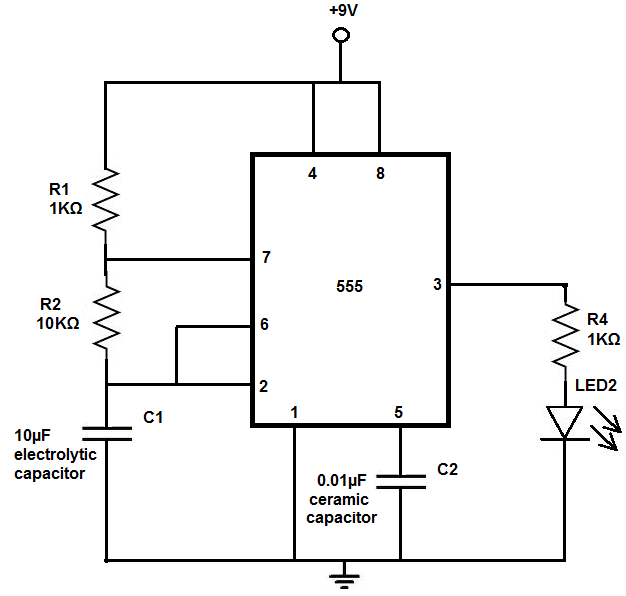
The 555 timer chip is a versatile integrated circuit (IC) that, when connected correctly, can generate pulses of current at specific intervals determined by a resistor-capacitor (RC) network. In this mode, the LED does not remain constantly lit; it...
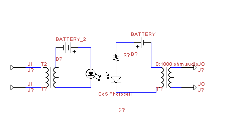
This circuit transmits audio information using light waves. It employs amplitude modulation (AM) to vary the intensity of an LED, which is detected by a cadmium sulfide photocell that changes its resistance based on light intensity. The circuit includes...

The VCO is based on a Hartley oscillator. The frequency is determined by L1 and capacitor C1. The tuning voltage will change the capacitance in the varactor BB132 which will change the oscillation frequency. The value of capacitor C2...
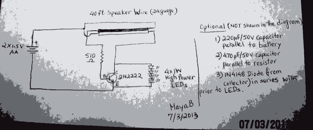
The post discusses a Joule Thief circuit that drives and illuminates four 1-watt LEDs using a single 1.5V pencil cell. The Joule Thief circuit is a minimalist boost converter designed to extract energy from low-voltage power sources, such as a...
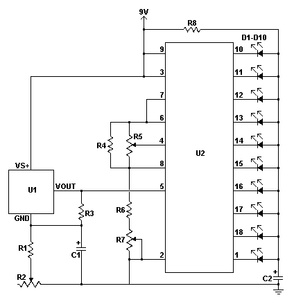
This LED thermometer is designed for in home use, to read temperatures between about 60 and 78 degrees Fahrenheit. It is based around a precision temperature sensor IC, the LM34DZ. This sensor require no calibration and can measure temperatures...

To create the circuit, connect a switch as an input and an LED as an output to the Arduino. The components required include a switch, an LED, a 10kΩ resistor, a 470Ω resistor, a blue or yellow jumper wire,...