
LEDs Revisited
LEDs are essential components in numerous electronic applications, serving as indicators, displays, and lighting sources. Their operational characteristics, such as size, color, and brightness, are critical for effective integration into circuits. The two common sizes, 3 mm and 5 mm, are often chosen based on the space available on a PCB (Printed Circuit Board) and the desired visibility of the LED in the final application.
When designing a circuit with LEDs, it is crucial to consider the forward voltage and current specifications to prevent damage. A resistor is typically placed in series with the LED to limit current flow. The resistor's value can be calculated using Ohm's Law, where the resistor value (R) is determined by the equation R = (Vs - Vled) / Iled, where Vs is the supply voltage, Vled is the forward voltage drop of the LED, and Iled is the desired forward current (in amperes).
In addition to calculating the resistor value, the layout of the circuit should ensure that the LED is properly oriented, with the anode connected to the positive side of the power supply and the cathode to the negative side. This prevents reverse polarity, which can damage the LED.
In applications requiring multiple LEDs, considerations regarding series and parallel configurations are necessary. In a series configuration, the same current flows through each LED, and the total forward voltage required is the sum of the individual forward voltages. In contrast, a parallel configuration allows each LED to operate independently, but care must be taken to ensure that the current through each branch is limited appropriately.
The choice of LED color and type directly impacts the application. For example, red LEDs are commonly used in indicators due to their visibility and low power consumption, while blue and white LEDs are favored in display applications for their brightness and color rendering capabilities.
Overall, understanding the specifications and characteristics of LEDs is vital for their effective use in electronic circuits. Proper design considerations will ensure reliable performance and longevity of the LED components in various applications.LEDs are available in a number of different sizes and shapes with most being round topped cylinders that are either 3 mm or 5 mm in diameter. These sizes are also commonly referred to as T1 (3 mm) and T1 (5 mm). The body of most LEDs is made of plastic that is either the same color as the lit LED, generally referred to as a diffused LED, or of a completely transparent plastic.
As a rule the clear LEDs are brighter than the diffused ones. The two LEDs on the left in this photo are diffused, the two on the right are clear. You can see the relative sizes of the 3mm and 5mm units, as well. Colors that are commonly available include red, orange, yellow or amber, green, blue and white. Infrared and ultraviolet LEDs are also available as are multicolored devices that can light with two or more colors. An LED`s color is frequently expressed as its wavelength. The shorter the wavelength, the closer the light is to the red end of the spectrum, the longer the wavelength the closer it is to the violet end.
(Do you remember Roy G. Biv ) A typical red LED has a wavelength of 660 nm (nanometers or billionths of a meter) Most LEDs have two metal wires extending from the back of the plastic body where they can be connected to a source of DC power. The longer lead is called the anode and is connected to the positive terminal of the power supply or battery.
The shorter lead is the LED`s cathode and is connected to negative. The base of the LED generally has a flat area next to the cathode which helps with lead identification if the wires have been cut. You can also identify the cathode by looking carefully at the insides of the LED. The cathode connects to the part that contains a dish shaped lens. Note that this is much easier to identify on the clear, non-diffused LEDs. In the photo below the cathode is on the right and the anode is on the left. If you look carefully you can see the dish in the center of the photo and the flat spot on the right side of the base of the clear plastic.
The voltage is a minimum of 1. 7 volts and a maximum of 2. 4 volts. This means that the LED will start to emit light at 1. 7 volts. The upper limit of 2. 4 volts does not mean that you could not power this LED with a higher voltage, it just indicates that you must include a resistor in the circuit should you use a higher voltage. The wavelength listed by Radio Shack is 660 mm. This is an error. It should read 660 nm. As mentioned earlier the wavelength refers to the color of the LED. The brightness is given as 800 MCD (microcandelas). This is not a particularly bright LED. You couldn`t use it for much more than an indicator or marker light. The viewing angle is 40 °, a fairly wide beam. The light emitted from some LEDs is focused to an angle of 30 ° or less. The most critical item in the list is the current limit which is given as 20mA (maximum). If more than 20mA is allowed to flow the LED will heat up and, if sufficient current is allowed to flow, the LED will be destroyed.
Resistors are generally used to limit the amount of current that can go to an LED. The value of the resistor that is needed can be determined in a number of ways. Please see last year`s article: A Simple Constant Brightness LED Light for a very detailed discussion of how this can be done. In theory one should mathematically or experimentally determine the pro 🔗 External reference
Related Circuits
A circuit was constructed based on an LED beating heart frame instructable, but it is not functioning as expected. There is also mention of a built LED sequencer. The LED beating heart circuit typically involves a microcontroller, such as an...
A request has been made to design a unique outdoor Christmas decoration in the form of an LED-illuminated star. The objective is to create a very bright display using 30 ultra-bright 8mm LEDs. The plan includes sanding the domes...
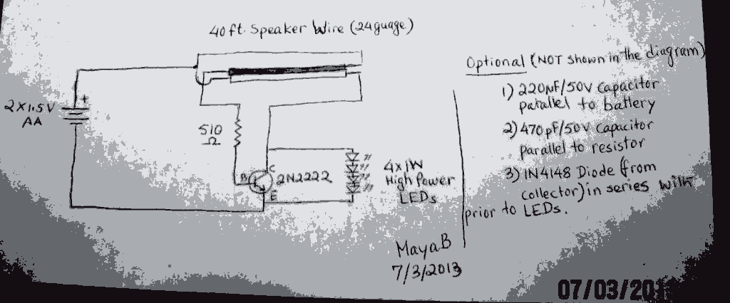
The post discusses a Joule Thief circuit that drives and illuminates four 1-watt LEDs using a single 1.5V pencil cell. The Joule Thief circuit is a minimalist boost converter designed to extract energy from low-voltage power sources, such as a...
This Project Multi-Pattern Running light is used to generate several designs of Running Lights. We use ten LEDs for display. The designs can be selected by using two switches UP and DOWN. The 8 bit Microcontroller is used to...
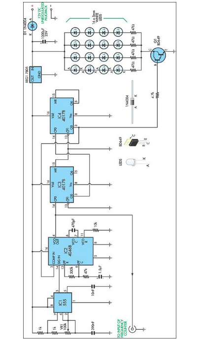
This stroboscope circuit utilizes 16 high-brightness white LEDs housed within a torch structure. It also offers a signal output to a frequency counter to indicate revolutions per minute (RPM). The stroboscope circuit is designed to provide visual indication of rotating...
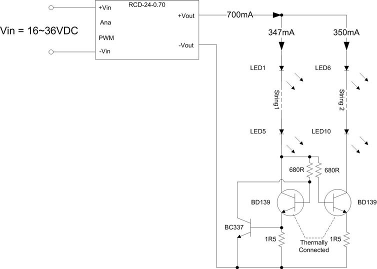
A Meanwell LED driver rated at 27V and 2300mA is available for use, intended to power two parallel strings of six LEDs each. The question arises whether to maintain the existing circuit with the same component values or to...
Warning: include(partials/cookie-banner.php): Failed to open stream: Permission denied in /var/www/html/nextgr/view-circuit.php on line 713
Warning: include(): Failed opening 'partials/cookie-banner.php' for inclusion (include_path='.:/usr/share/php') in /var/www/html/nextgr/view-circuit.php on line 713