
lets to build mini organ keyboard
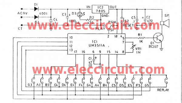
The UM3511 is a sound generator IC designed for generating audio tones. By connecting pin 5 to a transistor, a robust output can be achieved to drive speakers effectively. The transistor acts as a switch, amplifying the signal from the UM3511 to a level suitable for driving speakers, ensuring that the sound output is loud and clear.
The variable resistor (VR1) plays a crucial role in setting the frequency of the oscillator circuit within the UM3511. By adjusting VR1, the user can modify the pitch of the sound generated. This adjustment is essential for achieving the desired audio output, and once the correct frequency is determined, a fixed resistor can replace the variable resistor for stability in the circuit.
The inclusion of switch S1 provides flexibility in operation. This switch allows the user to select between different modes of sound generation. In one mode, the circuit can play pre-programmed music from the factory settings of the UM3511. In another mode, the user can input their own melodies using a keyboard, allowing for creativity and personalization in sound production. The keyboard interface can be designed to send signals corresponding to different notes, which the UM3511 interprets to produce sound.
Overall, this circuit design offers a versatile platform for sound generation, making it suitable for various applications, including educational projects, musical instruments, and sound effects in electronic devices. Proper component selection and circuit layout will ensure optimal performance and sound quality.We can connect a output of pin 5 on the UM3511-IC to drive a transistor output to emit loud sound out to the speakers directly. For the variable resistor-VR1 act as determine a frequency of the oscillator circuit. When we created successfully. Should be adjusted to the correct value. When adjusted, you may use the normal resistor instead. -The switch-S1 as an option act the work of circuit that music will be played by the application of the factory, or will play music as we have played own. From pushing keyboard as by various notes. 🔗 External reference
Related Circuits
This project is a fun and safe activity for individuals interested in magnetically launching projectiles. The operation involves placing a ferromagnetic projectile at one end of a coil and applying a power pulse. The key is to turn off...
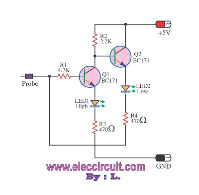
This logic probe circuit is designed for checking voltage levels in TTL circuits. It receives signals from the circuit being tested and indicates whether the logic level is high or low. When the input voltage at the probe tip...
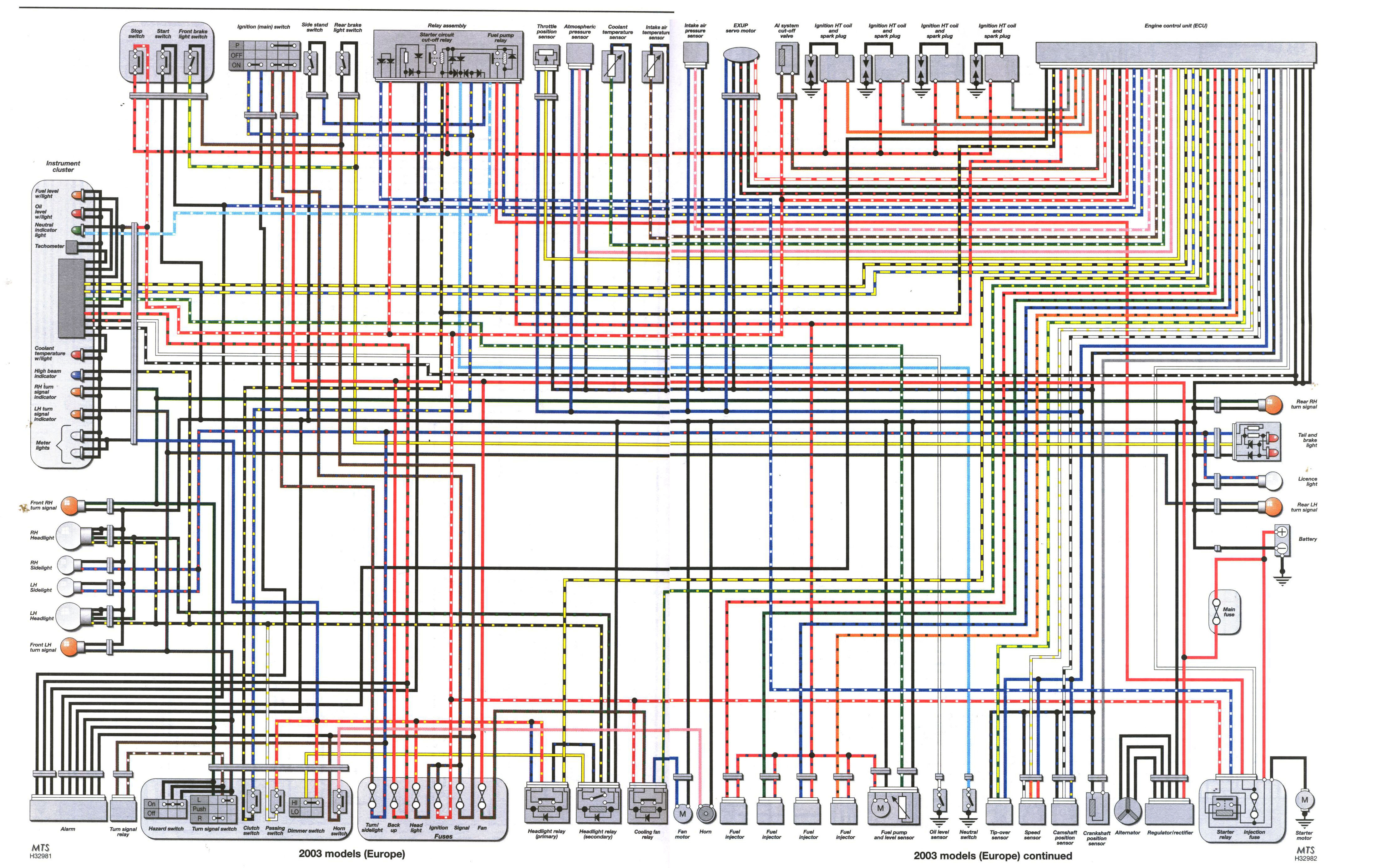
The plumbing and fuel system installations are complete, and final checks on the electrical system are currently in progress. The bike loom is being tidied up and tested. There is a query regarding two unused connectors in the 2003...

This version is V3.0, designed for TII use, featuring a stock FC ignition, a modified 24-2 style CAS, and a 3-bar MAP sensor. It has passed testing on the stimulator, indicating proper functionality. Future tests will be conducted on...
BattMan II is a computer-controlled battery manager designed for typical rechargeable batteries utilized by R/C and electronics hobbyists, as well as various consumer product batteries. BattMan II supports Nickel-Cadmium (NiCd), Nickel-Metal-Hydride (NiMH), Lithium-Ion (Li-Ion), Lithium-Polymer (LiPo), Lithium-Nano-Phosphate (LiNP), and...
The simple FM radio circuit was overlooked during the transition from vacuum tubes to transistors. In the late 1950s and early 1960s, several construction articles were published on building a straightforward superregenerative FM radio. After extensive research into these...
Warning: include(partials/cookie-banner.php): Failed to open stream: Permission denied in /var/www/html/nextgr/view-circuit.php on line 713
Warning: include(): Failed opening 'partials/cookie-banner.php' for inclusion (include_path='.:/usr/share/php') in /var/www/html/nextgr/view-circuit.php on line 713