
V3.0 MS Build With Pics
Warning: Undefined array key "extension" in /var/www/html/nextgr/view-circuit.php on line 477
Deprecated: strtolower(): Passing null to parameter #1 ($string) of type string is deprecated in /var/www/html/nextgr/view-circuit.php on line 477

The V3.0 circuit design is structured to support advanced ignition control and sensor integration. It utilizes a DB-37 connector for streamlined wiring, facilitating connections to various input and output devices. The board design incorporates pull-up resistors to stabilize signal integrity, particularly for ignition signal outputs. The inclusion of a 3-bar MAP sensor enhances the engine management capabilities by allowing for more precise monitoring of manifold pressure, essential for optimizing fuel delivery and ignition timing.
The modified 24-2 CAS is designed to provide reliable crankshaft position sensing, and the implementation of the built-in VR sensor conditioner is aimed at improving the accuracy of the signal processing. However, attention must be paid to potential noise interference, especially in environments with high electromagnetic interference, which can adversely affect the performance of the missing tooth decoder. Grounding practices are critical; it is recommended that all grounds be connected to a single point to minimize ground loops and potential noise pickup.
The use of twisted pair wiring, particularly in the context of the VR sensor connections, is encouraged to combat noise susceptibility. Shielding techniques, such as utilizing foil or braided wire, can provide additional protection against external electromagnetic fields. The circuit's design should also incorporate adequate filtering and decoupling capacitors to further enhance signal stability.
In summary, the V3.0 circuit represents a sophisticated evolution in ignition control technology, designed to accommodate modern engine management requirements while addressing the challenges posed by noise and electromagnetic interference. Proper assembly and attention to detail during installation are paramount to achieving optimal performance and reliability.This one is V3. 0, for TII use, stock FC ignition, 24-2 style modified CAS, and 3-bar MAP sensor. It tests fine on the stim, so I`m hoping all is well. I`ll power up my test bench later, and test with an actual 24-2 style CAS just to be sure. All wiring is via DB-37, no extra connectors needed. This is my first V3. 0 build, although I`ve built several V2. 2 and earlier styles. V2. 2 is a much easier build, as the board is less populated, and pad spacing, particularly on the little NPN transistors, is much more generous. Those of you that have built V3. 0 units before, let me know if anything looks odd. The only modification made to the board is the addition of the three pull-up resistors (those brown `DALE` resistors seen running vertical in the first couple pics), and associated wiring to bring the ignition signals out the DB37.
See attached pics for details. I used the prototype area as a pass-through, to get from the top to bottom side of the board, and ran the wires along the underside. The wiring should match the attached wiring schematic. Hey Renns, one thing you might want to be careful with using the 12-1 (24-2) setup, especially with the built-in VR sensor conditioner is noise.
The missing tooth decoder is a lot more sensitive to noise so far in my experience (using 12-1 in my 20 valve 4age on the ae86, and from what people using it that way have been telling me about their setups). I`ve had to do a lot to clean up EMI on the signal wires, make extra sure my grounds are good, make sure my relay grounds for various relay-driven components are separate from my MS grounds, and I`ve had to tinker with the threshold Potentiometer on the MS.
All that to get rid of a small amount of noise right at 6800-7000 rpms where the relay I`m running my VVT with turns off. Are you saying the 12-1 is more susceptible to noise than the using the stock CAS I`m not clear on that, as the input hardware is identical with missing tooth and 2nd trigger.
Did you mean the V3. 0 built-in VR circuit is more susceptible to noise than the LM1815 circuit That I can see, given the adaptive hysteresis feature of that chip. Hopefully with the proper grounds and shielding you mention, and following the VR circuit pot adjustment procedures here the install will run smoothly.
Hopefully these pics clarify the board mods required to support ignition output. Feel free to add these pic(s) to the FAQ if you like to supplement that older V2. 2 board pic. I`ve found the VR wiring to be the most important part in order to assure a noise-free signal. I`ve had zero problems using that intercom wire I`ve spoken of previously (twisted pair inside a braid and foil shield) as well as meticulous attention to being certain everything electrically connected is directly connected to a unified ground. This is regarding the v3 VR circuit. I`ve never had much luck with the 1815 circuits, I think primarily due to a 50KW AM radio station antenna 1/2 mile away from my home workshop.
They work fine as soon as I get away from that antenna. With a scope, I can see the AM signal in the inputs and it seems to confuse the 1815 in some way. 3) If you have a lot of random noise at one point or another, it`s easier to get nasty tach-spikes. I`ve seen as high as 20000 rpms when I`m really only at 6800. You can still get misses on the 2nd trigger wheel decoder if the Ne conditioner gets more pulses than it should. and you can still get tach spikes if the G conditioner gets more pulses tha 🔗 External reference
Related Circuits
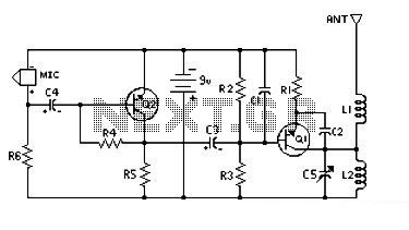
This is a low-cost and easy-to-build low-powered FM transmitter. The range of the FM transmitter is claimed to be about 300 feet when operating at a 9V supply. The range is said to increase to approximately 400 feet when...

This circuit is designed to test zener diodes. It connects to a 120V AC line and amplifies the output. The zener diode testing circuit operates by utilizing a transformer to step down the 120V AC line voltage to a more...

This circuit includes an intermittent siren output with an automatic reset feature. It can be manually operated using a key switch or a concealed switch, and it can also be configured to activate automatically when the ignition is turned...

The IR Beam Breaker Circuit Diagram is designed as an infrared beam breaking alarm suitable for use in entryways or passageways. This circuit utilizes the well-known IR sensor module TSOP 1738, which detects 38 kHz infrared pulses emitted by...
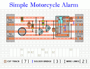
The following circuit is a simple, inexpensive, and easy-to-build motorcycle alarm. The circuit requires only two transistors to drive a relay, which acts as a switch to activate a buzzer. Any number of normally-open switches can be used. Mercury...
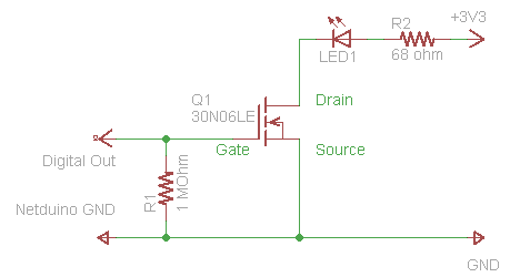
The process of driving an LED involves using a Power MOSFET to control the LED's state (On and Off) via a digital signal. This guide provides a step-by-step approach to wiring the circuit on a breadboard, which serves as...