
lf253 Frequency counter 1Hz-100Mhz with LCD display and RS232 interface
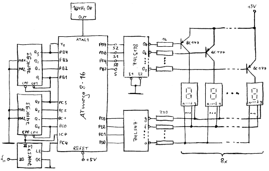
The schematic for the frequency counter integrates the AT90S4433 Microcontroller, the MAX903 comparator, and the aforementioned dividers. The AT90S4433 is powered by a stable 5V supply, with decoupling capacitors placed close to the power pins to mitigate noise. The input signal to be measured is connected to the 16-bit counter input pin PD5, while the output of the MAX903 comparator is linked to the clock input of the 16-bit counter, ensuring that the pulses are accurately counted. The LCD display, connected via a standard HD44780 interface, provides a user-friendly interface for displaying the frequency or event count. The RS232 interface is implemented using a level-shifting circuit to ensure compatibility with the Linux environment for data logging and analysis. The layout is optimized for minimal trace lengths, and the single-sided PCB design simplifies manufacturing while ensuring reliability. Overall, this frequency counter design provides a robust solution for measuring and counting signals in various applications, from hobby projects to more advanced electronic systems.This article continues the AT90S4433 Microcontroller series. I suggest you to read the previous articles on Atmel Microcontroller programming with regards to: This time we design a frequency counter which can measure frequencies from 1Hz to 100MHz. Alternatively you can use it also to just count events, such as how many people crossed the street ( what ever is available as a digital pulse). The counter has a LCD display as well as a RS232 interface to read out the counter results from Linux. The frequency of a sine wave or square wave signal is expressed as the number of oscillations per second.
In order to determine the frequency of a continuous signal one just needs to count those oscillations. This way we determine the frequency of the first harmonic of a continuously oscillating signal. To measure the frequencies that a non continuous "sound" is composed of, you need a spectrum analyser.
This is however a different piece of hardware. What we design here is a frequency counter for continuously oscillating signal. We assume that the signal does not change its frequency during a given interval where we sample the signal. 1 x MAX903 high speed voltage comparator, 8 Pin plastic DIP package, you can order it directly from in case your local dealer does not have it in stock.
All LCD displays that I have ever seen with 14 or 16 pins on the connector were HD44780 compatible. You can also use a 3 or 4 line display but then you will need to modify the software a bit. In addition to that you need some wires, connectors (BCD, power, RS232) and a 9V transformer or some other AC or DC power supply (150mA). Sometimes you get very cheap power supplies which plug directly into the wall socket and are used for all kind of consumer electronics.
I used eagle for Linux to design the schematic and board. The program has a few problems to understand that all the different power supply pins on the ICs are 5V. You will therefore get some error if you run the electrical rule check. The design is however correct. The board is specifically designed for hobby electronic. Only the blue layer is meant to be etched as a printed circuit board. The red lines are wires. It`s much easier and less accuracy is required to build a single sided printed circuit board. You can lay the wires (red) such that they have the shortest length. I could not do that in eagle. The AT90S4433 Microcontroller has two internal counters. One is 16bit wide and one is 8bit wide. We use the 8bit wide counter to generate an accurate time base from the frequency of the clock crystal of the AT90S4433.
For this purpose we use a 4194304Hz crystal and pulse the 8bit counter via a 1/256 internal pre-scaler (see data sheet of the AT90S4433, download at the end of the article). The 8bit counter is configured to generate an interrupt at overflow. In other words we get a 4194304Hz / (256 * 256) = 64Hz time base. By using a loop variable we generate from this functions calls in 1Hz intervals or 64Hz intervals. Now we have a function which is called in 1Hz or 64Hz intervals dependent on the mode our counter software is running at.
All we need to do now is read out the 16bit wide counter from this function and display the result. The 16bit wide counter (pin PD5 on the Microcontroller) gets its pulse signals from the signal that we want to measure. The Microcontroller samples the input signals to synchronize it with its internal clock. According to the sample theorem we can therefore maximum measure signals up to half the crystal frequency.
That`s the theoretical limit. In practice we can measure signals up to 1, 5MHz with the Microcontroller. To measure higher frequencies we need a pre-scaler/divider. This is what the 74F74 and the 74HC390 ICs provide. The 74F74 is used as a fast asynchronous 1/4 divider and the 74HC390 is a 1/25 divider. We can not use directly the 74HC390 as a 1/100 divider because it can handle max 25MHz. The circui 🔗 External reference
Related Circuits

The circuit is an easy-to-build and use general-purpose Big LED with SPI serial interfacing. It is expandable for multiple digits while utilizing only three wires to receive data from any microcontroller boards. The design incorporates a serial-in-parallel-out shift register,...
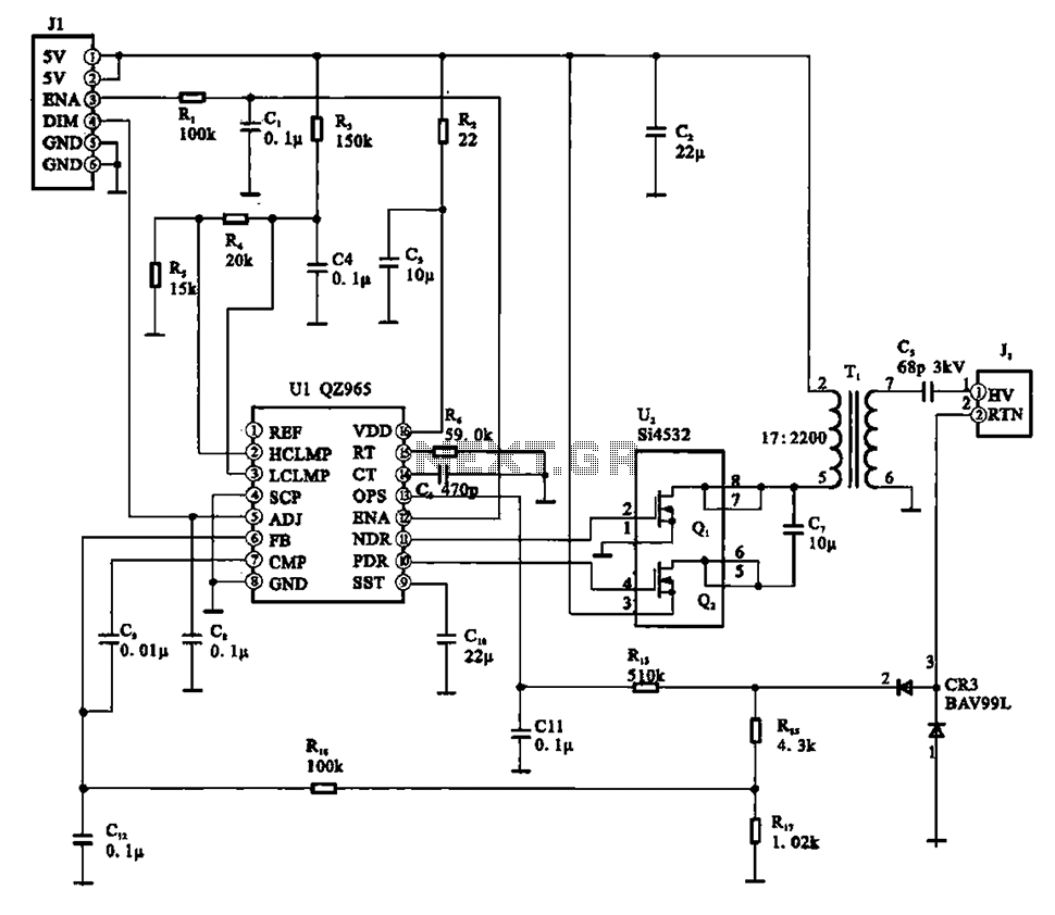
A typical liquid crystal display inverter circuit (OZ965) is primarily controlled by the OZ965 chip. It includes a driving field effect transistor (U2), a step-up transformer, the backlight socket, and associated circuitry. A 5V DC voltage is provided by...
In counter mode, it provides 1 Hz resolution up to 100 MHz. In timer mode, the maximum resolution is 0.0000001 Hz up to 1 Hz. The resolution decreases by one digit for each additional decade. Multiple frequency updates per...

The Wien bridge oscillator generates frequencies of 1 Hz and from 2 to 20 Hz in 2 Hz increments. The maximum output amplitude is 3 volts RMS or 8 volts peak-to-peak. A potentiometer and switch attenuator enable the output...
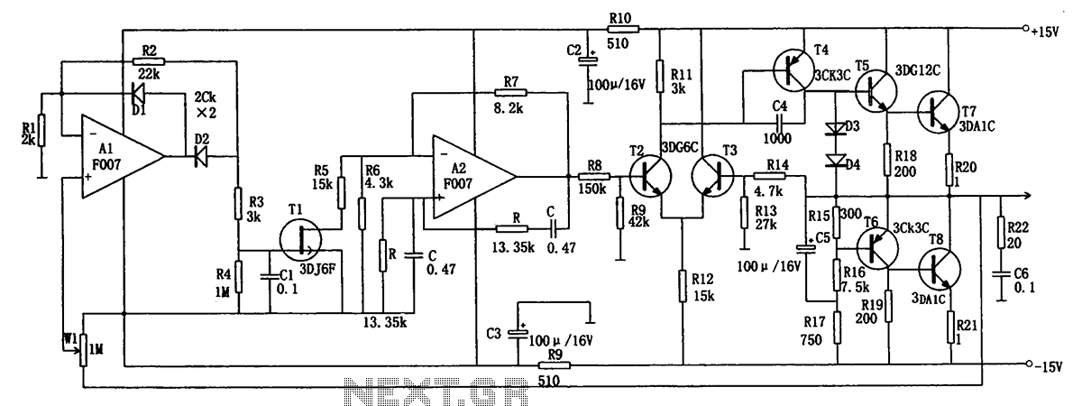
The low-frequency signal generating circuit demonstrates excellent performance characterized by stable operation, high output power, and minimal waveform distortion. It serves as an ideal source for low-frequency measurement signals. The circuit includes an operational amplifier (A) with a feedback...
This simple counter can be used to count pulses, as the basis for a customer counter (like you see at the doors of some stores), or for anything else that may be counted. The circuit accepts any TTL compatible...