
Light-Activated Alarm With Latch Circuit

This circuit operates primarily as a light-sensitive alarm system, utilizing a combination of resistors, transistors, and a silicon-controlled rectifier (SCR) to achieve its functionality. The light detection is facilitated by R5, which, upon exposure to light, allows current to flow through it. This current flow results in the forward biasing of transistor Q1, enabling it to conduct.
The sensitivity of the circuit is adjustable through R6, which can be varied to control the threshold at which the alarm is activated. This adjustment allows the system to be tailored for different lighting conditions or specific applications where light detection is required.
Once Q1 is activated, it provides the necessary emitter voltage to trigger SCR1. The SCR, a semiconductor device capable of controlling high power, remains latched once triggered, allowing current to flow to the alarm bell or buzzer (referred to as LQ1). This action results in the sounding of the alarm, alerting users to the presence of light.
To reset the alarm, a momentary press of switch S1 is required. This action interrupts the current flowing through SCR1, effectively unlatching it and silencing the alarm. It is crucial to implement a self-interrupting alarm mechanism, such as an electromechanical buzzer or bell, to ensure that the alarm can operate independently without additional manual intervention after it is triggered.
Overall, this circuit serves as an effective light-detection alarm system, combining simplicity with functionality, making it suitable for various applications where light monitoring is essential. In this circuit, light causes R5 to conduct forward-biasing Ql. R6 sets sensitivity. SCR1 is triggered from the emitter voltage on LQ1, sounding the alarm bell. When SI is depressed, SCR1 unlatches. Be sure that a self-interrupting alarm (electromechanical buzzer or bell) is used. 🔗 External reference
Related Circuits
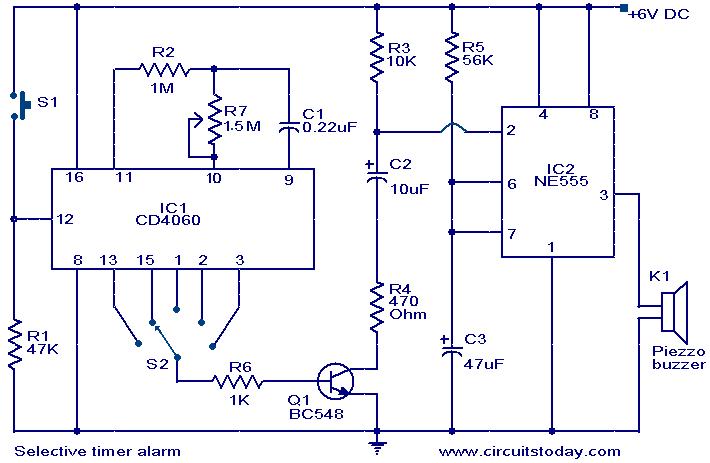
The following circuit illustrates a Selective Timer Alarm Circuit based on the 4060 Integrated Circuit (IC). Features include an automatic turn-off mechanism for the alarm after a specified duration. The Selective Timer Alarm Circuit utilizes the 4060 IC, which serves...
This device emits intermittent beeping for approximately two seconds when a whistle is detected from a person within a range of around 10 meters. The first two inverters in IC1 function as audio amplifiers. IC1A amplifies the signal captured...
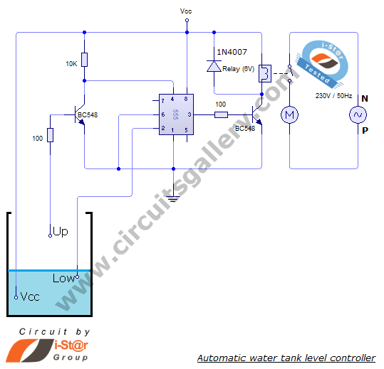
The automatic water level controller circuit is a straightforward engineering project that can automatically switch a domestic water pump on and off based on the water level in a tank. This motor driver circuit can be implemented at home...

This circuit is designed to detect the approximate percentage of salt contained in a liquid. After careful calibration, it provides a quick, rough indication of the salt content in liquid foods for dietary purposes. The circuit utilizes the LM324...
The LA4440 is a two-channel audio power amplifier integrated circuit (IC) designed for stereo and bridge amplifier applications. In dual mode, it provides an output of 6 watts per channel, while in bridge mode, it can deliver up to...
This circuit is a digital panel meter (DPM) featuring an analog bar graph display and a 3.5-digit digital display. The ICL7107 is configured for 200mV input. The U4A operational amplifier (LF353) amplifies the 200mV full-scale input to the required...