
Light Activated Switch

The light-activated switch circuit utilizes a light-dependent resistor (LDR) as the primary sensing element to detect ambient light levels. When the ambient light intensity falls below a predetermined threshold, the resistance of the LDR increases, triggering the circuit to switch off the connected lamp or lamps. This functionality is particularly useful in applications where automatic control of lighting is desired, such as in outdoor lighting systems or energy-saving applications.
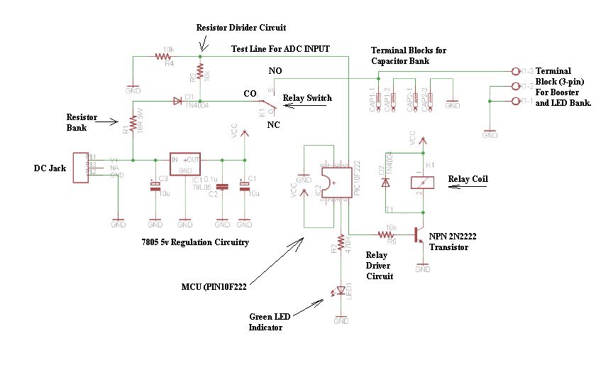
The circuit typically includes a power supply, an LDR, a comparator or operational amplifier, and a relay or transistor to control the lamp. The LDR is connected to a voltage divider configuration, which allows the output voltage to vary based on the light intensity. The comparator compares this output voltage to a reference voltage set by a potentiometer. When the LDR's voltage falls below the reference voltage, the comparator activates the control element, either a relay or a transistor, to disconnect the power from the lamp.
Additional components may include a capacitor for noise filtering, diodes for reverse voltage protection, and resistors to limit current through the LDR and control the sensitivity of the circuit. The design can be further enhanced with adjustable thresholds for light sensitivity and time delays to prevent flickering due to transient light changes.
This circuit provides an efficient solution for automatically managing lighting based on environmental conditions, contributing to energy conservation and convenience in various applications.The light activated switch circuit can be used for switching OFF a particular lamp or group of lamps in response to the varying ambient light levels. The u.. 🔗 External reference
Related Circuits
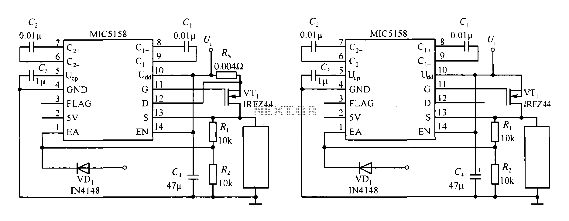
The MIC5158 is part of a high-speed switching circuit diagram that focuses on the rising edge. The MIC5158 is a precision voltage reference and high-speed switching device that is commonly utilized in various electronic applications requiring rapid signal transitions. In...

The receiver section was not illustrated as it is considered standard. The TRIAC switch section depicted below can be controlled using standard 4000 series CMOS logic. The TRIAC switch section operates by utilizing a TRIAC (Triode for Alternating Current) component,...
The circuit uses a 555 timer wired as an astable oscillator and powered by the emitter current of the BC109C. Under dry conditions, the transistor will have no bias current and be fully off. As the probes get wet,...
The schematic of the SAVER V3.2 is depicted in Figure 1. A transformerless power supply uses Xc of a 0.22uF capacitor to limit current, providing about 10mA current source. The diodes rectify AC current to DC current, which in...
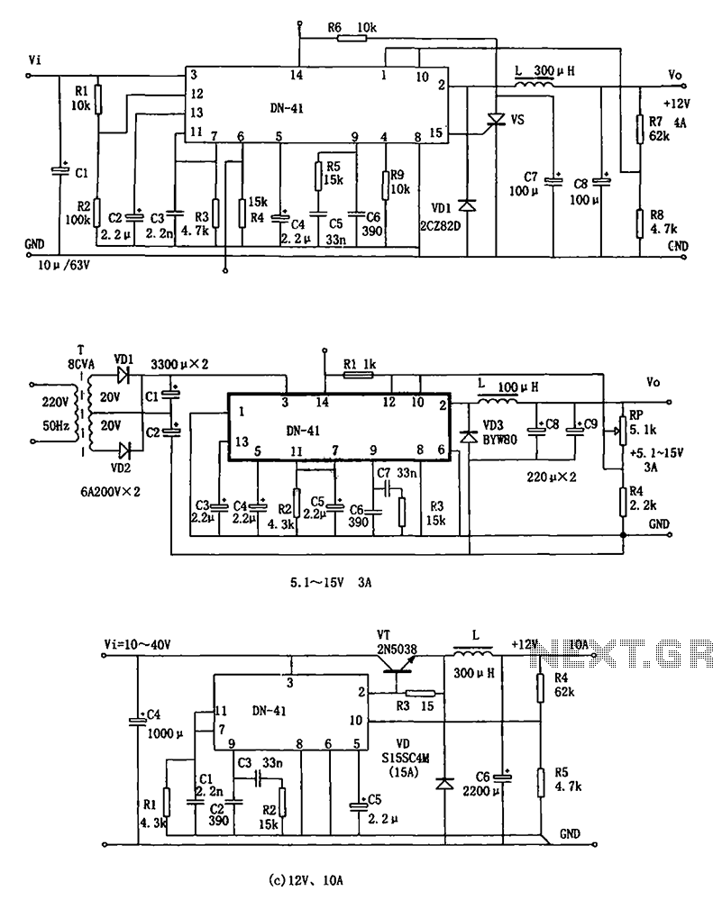
The DN-41 is a high-current switching regulator that includes an overcurrent and overvoltage (crowbar) protection circuit, a reset circuit, and a soft start feature. It is designed to operate with fewer external components while maintaining stability, safety, and reliability....
The schematic consists of four hardware blocks: 1) The wall transformer 2) The charging circuit 3) The control unit 4) The output stage. The circuit schematic is structured around four essential hardware blocks that facilitate the overall functionality of the...