
pump it up mp3 booster

The MP3 booster circuit is designed to enhance audio output from portable MP3 players, facilitating a seamless connection to Hi-Fi systems for shared listening experiences. The circuit employs a dual-channel amplifier configuration using the TS922IN op-amp, which is well-suited for low-voltage operations. The gain settings of three and ten times are adjustable via jumpers, allowing users to tailor the amplification based on the audio source's output level.
The input stage of the circuit utilizes a stereo socket (K1) to receive audio signals from the MP3 player. These signals are then fed into the op-amp inputs, where they undergo amplification determined by the feedback network formed by resistors R1, R2, R5, and R6. The design effectively mitigates issues related to parasitic capacitance by incorporating output resistors (R4 and R8), which stabilize the output and prevent unwanted oscillations that can arise from long cable runs.
The output stage connects to the Hi-Fi system through phono sockets (K2 and K3), ensuring compatibility with standard audio equipment. The choice of rechargeable batteries not only provides portability but also aligns with sustainability practices, allowing for repeated use without reliance on disposable batteries.
Overall, the MP3 booster circuit represents a practical solution for enhancing the audio experience of portable music players, enabling users to enjoy high-quality sound in a social setting while maintaining user-friendly operation and adaptability to various audio sources.MP3 players are all the rage these days. The smaller ones in memory-stick format are particularly easy to take with you; your very own personal sound system` on the move! It`s when you want others to share your taste in music that you ¬nd these players to have a lack of power.
You can get round this problem with the help of the MP3 booster, a small amplifier that c an be used to connect your MP3 player directly to your Hi-Fi. When you next invite your friends to a party you can ask them to bring their personal music` as well as the usual drinks! But ¬rst we have to build this booster! The small battery-powered players have an output signal that is more than suf ¬cient to drive a set of 32 Ohm headphones.
You`ll often ¬nd that with an output of 1mW the sound pressure level (SPL) produced can reach up to 90 dB. This would be suf ¬cient to cause permanent damage to your hearing after only one hour! The maximum output voltage will then be around 200mV. This, however, is insuf ¬cient to fully drive a power amplifier. For this you`ll need an extra circuit that boosts the output voltage. Power amps usually require 1 V for maximum output, hence the signal has to be ampli ¬ed by a factor of ¬ve.
We will also have to bear in mind that quieter recordings may need to be ampli ¬ed even more. We`ve used a simple method here to select the gain, which avoids the use of potentiometers. After all, the MP3 player already has its own volume control. We decided to have two gain settings on the booster, one of three times and the other ten times. Ampli ¬ers IC1A and IC1B (for the right and left channels) are housed in a single package, a TS922IN. The output signal of the MP3 player is fed via a stereo cable and socket K1 to the inputs of the amplifiers.
The gain depends on the relationship between resistors R2 and R1 (R6 and R5 for the other channel) and is equal to ten times. When you add jumper JP1 (JP2), resistor R3 (R7) will be connected in parallel with the negative feedback resistor R1 (R6), which causes the gain to be reduced to about three.
When you start using the booster you can decide which gain setting works best for you. Resistor R4 (R8) takes the ampli ¬ed MP3 signal to the output socket K2 (K3). A cable then connects these phono sockets to the input of your power amplifier. The resistors connected in series with the output (R4 and R8) are there to keep the booster stable when a long cable is connected to its output. Cables have an unwelcome, parasitic capacitance. This capacitive effect could (due to phase shifts of the signal) affect the negative feedback of the booster in such a way that a positive feed back occurs, with the result that the booster oscillates and possibly damages the power amplifier!
The resistors (R4 and R8) effectively isolate the output of the booster from the parasitic capacitance of the output cable. They also protect the booster outputs from short circuits. We`ve used a TS922IN opamp in this booster because it can operate at very low supply voltages (the maximum is only 12 V!), but can still output a reasonable current (80 mA max.
). For the supply we`ve used rechargeable batteries (e. g. NiCd or NiMH cells) so that we don`t need a mains supply. To keep the number of cells required as small as possible, we`ve chosen a supply voltage of 5 volt; this can be supplied by four rechargeable batteries. It is also possible to use four ordinary, non-rechargeable batteries; it`s true that the supply voltage then becomes a bit higher (6 Volts), but that won`t cause any harm.
Since we`ve used a symmetrical supply for the booster (2 x 2 batteries), it will be easiest if you use two separate battery holders, each with two AA cells. The two holders are connected in series. Make sure that the batteries are connected the right way round; the positive of one always has to be connected to the negative of the next.
This also applies to the connection betwe 🔗 External reference
Related Circuits
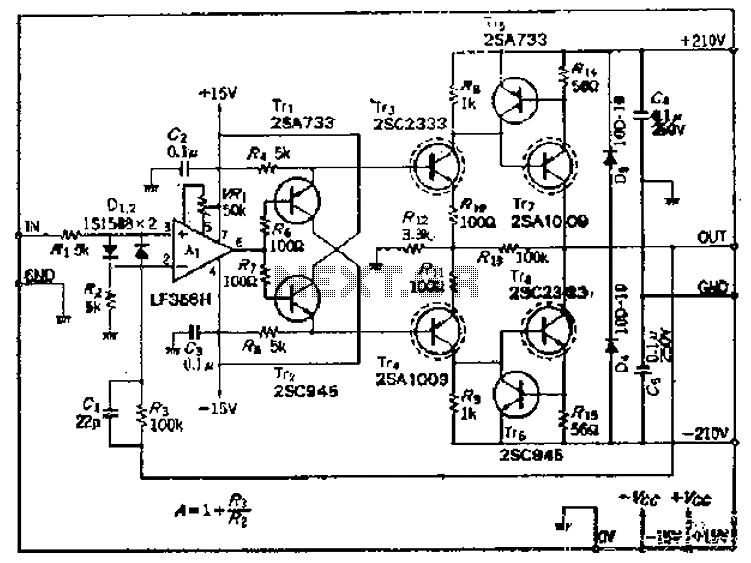
This amplifier circuit operates with an OP amplifier that is power-driven, which leads to the presence of floating voltage errors and necessitates a high-pressure booster for transistor protection. The circuit utilizes a mutual feedback configuration, connecting to the output...
The two unspecified polarized capacitors (one directly above the transformer and one directly to the right of the transformer) are actually each a pair of 470 µF capacitors in parallel (for a total of four 470 µF capacitors). These...

It is possible to enhance fuel pump performance, but can adjustments be made to the wiring of an external pump to reduce fuel flow? This inquiry arises while assisting with an engine swap, specifically installing a 4AGE engine in...
This process can be simplified by utilizing a display kit from PJRC, which includes the appropriate firmware installed on the display, a functioning pushbutton board, and the necessary cables. The PJRC display features a 4-pin connector compatible with the...
This circuit is a 20W Audio Amplifier kit, based on the TDA2005 IC, a class B dual audio amplifier, specifically designed for car radio applications etc. Power supply - 18 VDC. Output power - 20 W, 4 ?. IC...
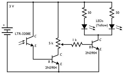
The concept involves placing a pair of yellow LEDs inside a pumpkin, combined with a photo sensor that activates the lights at night. The circuit is simple, utilizing minimal components. Two schematics are provided on the project site, with...