
Light Dark switch activated relay circuits
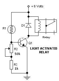
The light-dark switch activated relay circuit operates by utilizing a photoresistor (R1) that detects ambient light levels. When the light intensity falls below a predetermined threshold, the resistance of the photoresistor increases, which alters the voltage at the base of the transistor (Q1). This transistor acts as a switch, controlling the relay's coil. The relay, when activated, can then power other devices, such as lights or alarms, depending on the application.
The R2 potentiometer allows for fine-tuning of the sensitivity of the circuit, enabling the user to set the exact light level at which the relay should activate. The diode (1N914 or 1N4001) is connected in parallel with the relay coil to protect the circuit from back EMF generated when the relay is de-energized. This protection is crucial for maintaining the longevity and reliability of the circuit components.
The circuit can be powered with a low voltage supply, typically between 5 to 6 volts, which is suitable for small electronic devices. The use of a 2N2222 transistor or its equivalents ensures that the circuit can handle the required current to activate the relay while providing sufficient gain to operate effectively. The overall simplicity of this design makes it an excellent choice for various applications, such as automatic lighting systems, garden lights, or security alarms, where activation based on light conditions is desired.This Light Dark switch activated relay circuits schematics are the simplest electronic circuits that can help you to activate other electronic device at the light or dark. This Light Dark switch activated relay circuits are very simple and require one electronic relay and other few common components that are not critical.
For electronic project you need to use a 5-6 volts electronic relay. The R2 potentiometer is used to adjust the trigger on level. The diode in the diagram shows to be 1N914. This is ok if you have a light-duty relay, also the 1N914 is a signal diode so actually does not qualify. If you don`t find the 1N914 you can substitute it with a 1N4001 diode (or better) instead. The 2N2222 (Q1) transistor can be substitute with :NTE123A, ECG123A, PN100, or other similar types. The R1 component is a photo resistor. 🔗 External reference
Related Circuits
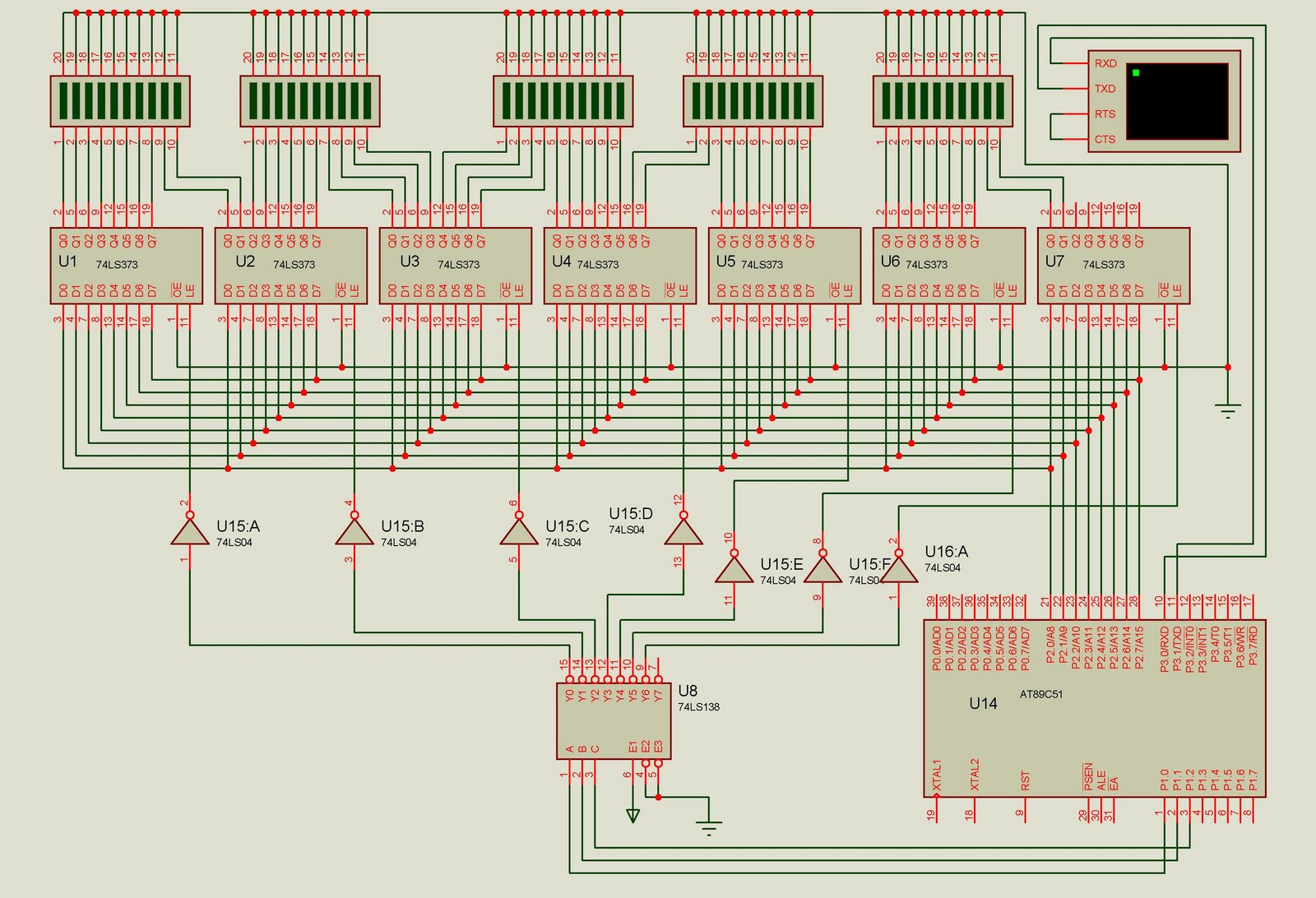
This project is designed to control up to 50 solid-state relays independently. It serves as an excellent learning resource for students who wish to expand the input-output lines of a microcontroller and control multiple devices. The ON or OFF...
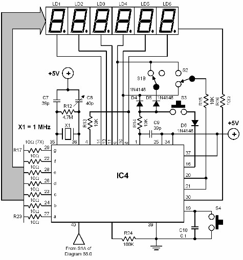
A digital audio frequency (AF) counter can be constructed using a minimal number of components by employing a single 7226B integrated circuit (IC) from Intensil, as depicted in the accompanying diagram. This circuit has an upper frequency limit of...
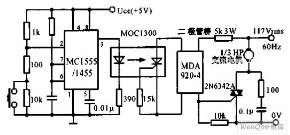
The switch shut-off time delay circuit consists of a timer, optocouplers, a bridge SCR, and an SCR AC switch. When the control button is released, it allows the motor or other AC power to remain active for one hour....
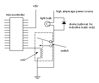
Digital output from a microcontroller is typically a low-amperage signal. For example, when a pin is set HIGH on the microcontroller (in Wiring/Arduino, it is digitalWrite(somePin, HIGH);), the voltage from that pin is usually +3.3V or +5V, with the...
This is a high-frequency switch circuit. This circuit utilizes the 2N4391 transistor. When in the off state, it provides a high off-impedance of less than 0.2 pF and exhibits a low on-resistance. The high-frequency switch circuit designed with the 2N4391...
A useful operation for the cars is delayed extinguishing internal lighting cabin of passengers, after close some door of car. Certain cars allocate this operation from their constructor. Oldest sure do not allocate such operation. This delay makes this...