
Single transistor phase shifter

The circuit utilizes a transistor configured as a phase splitter, which is a common arrangement in analog electronics. The transistor's configuration allows it to produce two outputs: one that is inverted (180° phase shift) and another that maintains the same phase as the input signal. This is achieved by connecting the input signal to the base of the transistor, where it is amplified and split into two distinct outputs.
At point A, the output is taken from the collector of the transistor, which provides the inverted signal. Conversely, point B, connected to the emitter, delivers the non-inverted signal. The phase relationship between these two outputs is critical for applications requiring precise phase control, such as in audio processing or signal modulation.
The resistor R1 plays a pivotal role in adjusting the phase shift. By varying the resistance value, the relative proportions of the output signals at points A and B can be manipulated. This adjustment allows for a continuous transition between the two phase states, enabling fine-tuning of the phase shift according to the specific requirements of the application.
The operational frequency range of 600 Hz to 4 kHz indicates that this circuit is well-suited for audio applications, where phase relationships can significantly impact sound quality and spatial effects. The design ensures that the circuit maintains stability and performance within this frequency range, making it ideal for use in audio signal processing, synthesizers, and other electronic devices requiring phase manipulation.
In summary, this circuit is a versatile tool for generating variable phase shifts, leveraging the properties of a transistor to provide both inverted and non-inverted outputs, with the ability to finely adjust the phase relationship through the use of a variable resistor.This circuit provides a simple means of obtaining phase shifts between zero and 170°. The transistor operates as a phase splitter, the output at point A being 180° out of phase with the input. Point B is in phase with the input phase. Adjusting Rl provides the sum of various proportions of these and hence a continuously variable phase shift is provided
The circuit operates well in the 600 Hz to 4 kHz range.
Related Circuits
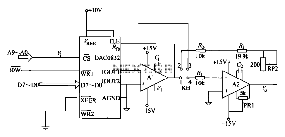
The DAC0832 is a digital-to-analog converter (DAC) chip designed for integration with computer bus systems. It features an 8-bit resolution and operates with a single power supply ranging from 5 to 15 volts. The device is compatible with TTL...
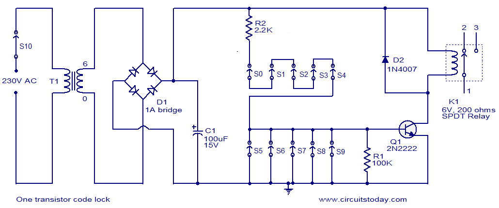
This is a simple electronic code lock circuit that can be easily constructed. The circuit consists of one transistor, a relay, and several passive components. Its simplicity does not compromise performance, and it functions effectively. The circuit operates as...
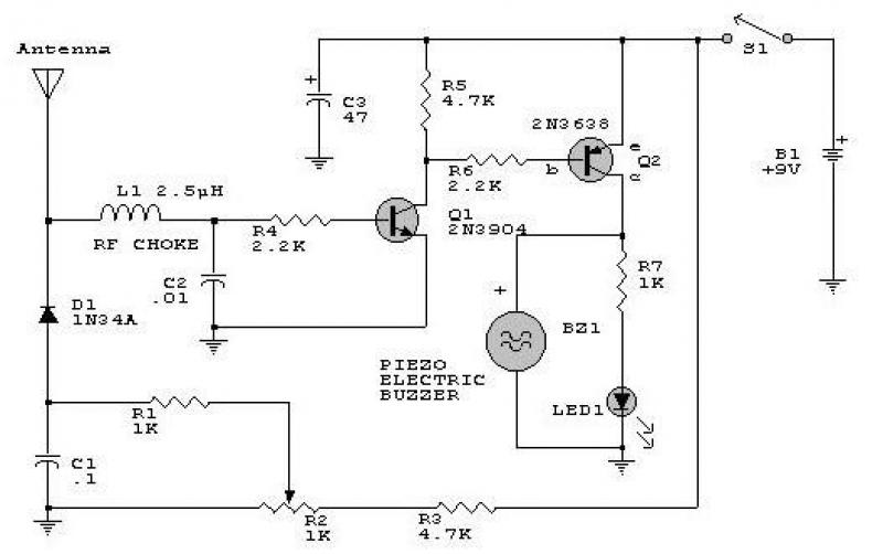
This circuit responds to RF signals below the standard broadcast band up to over 500 MHz and provides both visual and audible indications when an RF signal is detected. By adjusting the bias of diode D2 with the R2...

This is a water sensor circuit design based on a Conductive Liquid Level Sensor. This single-chip circuit is compact and simple. It is an AC-excited fluid level sensor, which uses alternating current to provide biasing for the sensor probe,...
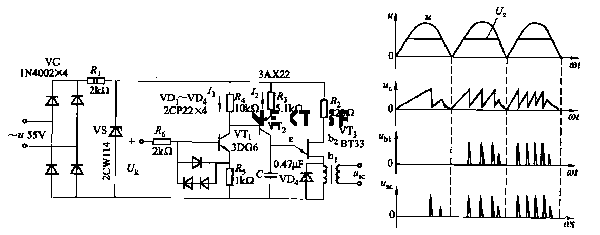
Due to the increased level of the transistor amplifier circuit, the control circuit's performance in Figure 16-6 is more sensitive and can accept input control signals superimposed on others (such as voltage, current, and speed feedback signals) to meet...
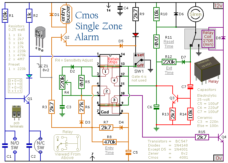
This circuit features automatic Exit/Entry delays, timed Bell Cut-off and System Reset. It has provision for normally open and normally closed switches and will accommodate the usual input devices such as Foil Tape, Pressure Mats, Magnetic Reed Contacts, Passive...