
Light-sensitive Alarm Project
The described circuit functions as a shadow detection alarm system, utilizing a light-dependent resistor (LDR) as the primary sensing element. The LDR's resistance varies significantly with light intensity, allowing the circuit to detect rapid changes in illumination caused by an object blocking the light source. The design intentionally avoids responding to slow changes in light to minimize the occurrence of false alarms, ensuring reliability in various lighting conditions.
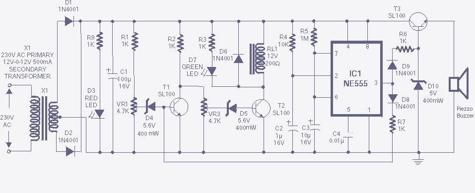
The core of the circuit is built around the 7555 timer IC, which is a low-power version of the popular 555 timer. This choice of IC is crucial for maintaining low power consumption, as it allows the circuit to operate efficiently while drawing minimal current during idle states. The timer is configured in a monostable mode, which means it will output a high signal for a predetermined duration when triggered by the LDR detecting a sudden drop in light intensity.
When the light beam directed at the LDR is interrupted, the resistance of the LDR increases sharply, causing the voltage across it to drop below a certain threshold. This change triggers the 7555 timer, which in turn activates the bleeper. The bleeper is designed to sound only for a short period, which not only serves to alert the user but also helps to conserve battery life, a critical feature for portable applications.
The power management strategy of the circuit is noteworthy. The use of a 9V PP3 battery allows for a compact design, while the option to use six AA alkaline batteries provides an extended operational life. The estimated battery life is based on continuous operation, with the circuit drawing approximately 0.5mA during idle periods and 7mA when the bleeper is activated. This design consideration is vital for applications where the circuit may be left on for extended periods without user intervention.
Overall, this circuit combines effective light sensing, efficient power management, and user-friendly operation, making it suitable for various applications where shadow detection is required.The circuit detects a sudden shadow falling on the light-sensor and sounds the bleeper when this happens. The circuit will not respond to gradual changes in brightness to avoid false alarms. The bleeper sounds for only a short time to prevent the battery running flat. Normal lighting can be used, but the circuit will work best if a beam of light i s arranged to fall on the light-sensor. Breaking this beam will then cause the bleeper to sound. The light sensor is an LDR (light-dependant resistor), this has a low resistance in bright light and a high resistance in dim light. Using the 7555 low-power timer ensures that the circuit draws very little current (about 0. 5mA) except for the short times when the bleeper is sounding (this uses about 7mA). If the circuit is switched on continuously an alkaline PP3 9V battery should last about a month, but for longer life (about 6 months) you can use a pack of 6 AA alkaline batteries.
🔗 External reference
Related Circuits
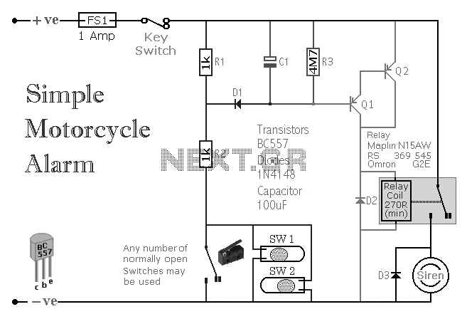
A simple transistor-based motorcycle alarm circuit. This circuit is easy to build and designed to operate at 12 volts. However, by replacing the relay with one that has a 6-volt coil, it can also provide protection at that voltage. The...

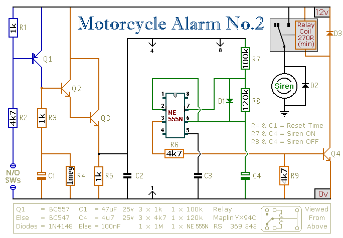
This circuit utilizes two 555 timers to generate a low-frequency tone that gradually increases to a high-frequency tone over the course of approximately 1 second. Following this, the sound ceases for about 0.3 seconds before the cycle begins anew....

The circuit consists of a triggering device, a monostable delay circuit, an alarm sound generator, an audio amplifier circuit, and a light control circuit, with a partially blocking preset circuit and power circuit. When the door is locked and...
This circuit features an intermittent siren output and automatic reset. It can be operated manually using a key switch or a hidden switch; however, it can also be wired to activate automatically when the ignition is turned off. By...
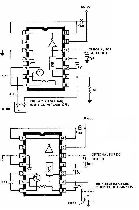
This electronic liquid detector circuit diagram is based on the ULN2429 monolithic bipolar integrated circuit designed for detecting the absence or presence of many different types of liquids. The ULN2429 electronic liquid detector circuit can be used in automotive,...
The high and low voltage cut-off with delay and alarm circuit, along with its circuit diagram, is explained in this post. The high and low voltage cut-off circuit is designed to protect electrical devices from damage caused by excessive voltage...
Warning: include(partials/cookie-banner.php): Failed to open stream: Permission denied in /var/www/html/nextgr/view-circuit.php on line 713
Warning: include(): Failed opening 'partials/cookie-banner.php' for inclusion (include_path='.:/usr/share/php') in /var/www/html/nextgr/view-circuit.php on line 713