
Light sensor using Op Amp

In this setup, the LDR replaces R2 in the resistor network. As light intensity increases, the resistance of the LDR decreases, leading to a decrease in voltage, and vice versa. Alternatively, if the LDR is connected in place of R1, the output voltage will decrease with lower light intensity. A variable resistor is also incorporated, connected to the other input terminal of the Op Amp, serving as a reference voltage for comparison with the voltage from the resistor network. This variable resistor, or potentiometer, is manually adjusted to ensure that its output voltage is slightly above or below the voltage from the resistor network.
To achieve the desired circuit functionality, the variable resistor must be tuned so that its output voltage is just below that of the resistor network. This tuning process is straightforward; the potentiometer is adjusted until an LED connected to the output of the Op Amp just lights up. When a shadow is cast over the LDR, the LED will turn off. It is essential to perform this adjustment under the same lighting conditions in which the circuit will operate. Additionally, modifications can be made to reverse the operation, enabling the LED to turn on in the presence of a shadow. This can be accomplished by swapping the connections of the inverting and non-inverting terminals of the Op Amp, which correspond to its second and third pins.
This circuit design effectively demonstrates the principles of light detection and voltage comparison using an Op Amp, making it suitable for various applications in robotics and automation. The LDR's response to light changes allows for dynamic control based on environmental conditions, while the adjustable potentiometer offers flexibility in setting the threshold for activation.A light based sensor using an LDR (Light detecting resistor) and ofcourse an Op Amp. You can use this circuit to make line followers and other stuff. Here we go: Since we are using an op amp to compare we should first be clear about its functioning. Basically an Op Amp has two inputs, an inverting input and a Non-Inverting input. If the voltage at the Non-Inverting input(Denoted by +) is greater than the input voltage at the inverting input(Denoted by -) the output of the Op Amp will be High, ie. , 5 Volts. But if the voltage at the non inverting terminal (+) is less than the voltage at the inverting input terminal (-) then the output will be Low ie.
, 0 Volts. As the value of the resistors is what the voltage depends on, it should understood by now that any change in resistance leads to a change in voltage. Not its time to welcome the LDR in the scene. In the above resistor network replace R2 with the LDR. Now with the increase in the light intensity the resistance of LDR decreases which leads to the decrease in voltage and viceversa The whole theory turns upside down if we connect the LDR in the place of R1, ie.
, The output voltage decreases with a decrease in the light intensity and vice versa. Using the same voltage division principle we use a variable resistor and connect it to the other input terminal of the Op Amp. This will be the reference to which the Op Amp will compare the voltage from the resistor network. We manually tune the potentiometer using a screw driver, so that the voltage given by it will be slightly above or below the voltage given by the resistor network.
To get the above circuit we should tune the Variable resistor using a screw driver or a knife so that the Vout of the variable resistor is just below the Vout of the resistor network. Doing that is not as complicated as it sounds, You should just have to turn the potentiometer til the LED just lights up and stop.
Now if you put your hand over the LDR and cast some shadow over it, the LED turns off. It is necessary that you keep the circuit in the light conditions where you will be operating it while you tune it. Also you can make modifications in this circuit and make it turn on when there is a shadow. This can simply be done by interchanging the inverting and the Non-Inverting terminals of the Op Amp.
Which are the 2nd and the 3rd pins. 🔗 External reference
Related Circuits
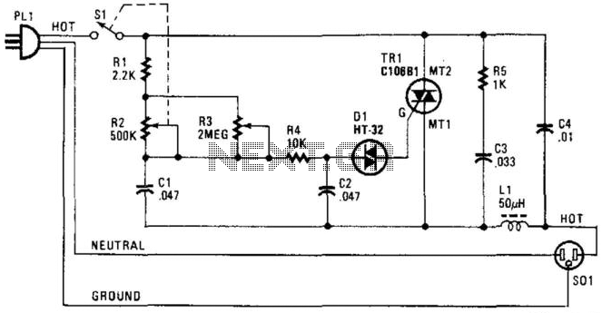
A phase-controlled triac (HT-32) circuit offers control over the effective voltage at the load. It is important to include LI and C4, as they are essential for RFI suppression. The maximum load capacity is approximately 500 W. WARNING: 120...
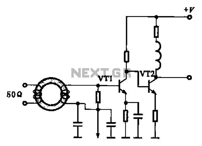
A broadband high-frequency amplifying circuit is primarily composed of a high-frequency matching transformer and an amplifying transistor. This circuit is designed to handle large high-frequency signals. The input of the amplifier circuit utilizes a matching transformer to ensure that...
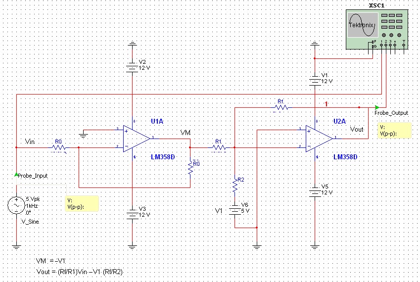
All naturally occurring phenomena such as sound, temperature, and pressure are analog in nature. To enable a microcontroller to read analog signals for the analog-to-digital conversion process using a built-in analog-to-digital converter (ADC), it is essential to condition the...
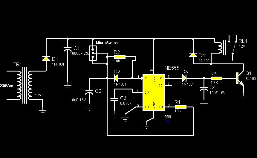
The circuit diagram illustrates a rotation sensor that activates a device, such as a motor or buzzer, when the circuit assembly is rotated. The design is based on the fundamental operation of a 555 timer. The rotation sensor circuit utilizes...
This project provides a simple temperature-controlled fan. If the difference between the actual temperature and the user-defined temperature is significant, the fan will operate. The temperature-controlled fan circuit utilizes a temperature sensor, a microcontroller, and a fan motor to regulate...
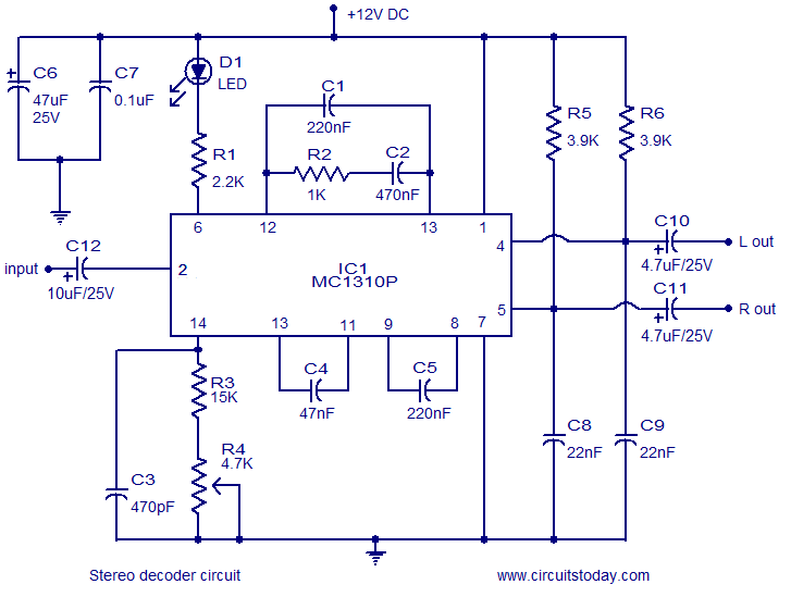
A simple FM stereo decoder circuit utilizing the MC1310P integrated circuit (IC). It operates at 12V and provides a channel separation of 40dB, making it suitable for stereo FM receivers. The FM stereo decoder circuit based on the MC1310P IC...