
Music Driven Motor Schematic

The music-driven motor schematic involves a geared motor that is activated in response to sound signals, specifically music. This design typically incorporates a sound sensor, which detects the amplitude of the music and converts it into an electrical signal. The output from the sound sensor is then processed to control the geared motor, allowing it to move in sync with the rhythm of the music.
Key components of the schematic may include a microcontroller or an operational amplifier to filter and amplify the sound signals, ensuring that only the desired frequencies are used to drive the motor. A pulse-width modulation (PWM) technique can be employed to adjust the speed and movement of the motor, enabling it to create dynamic motion that mimics the dancing flower's movement to the beat.
The geared motor is selected based on the required torque and speed to effectively move the flower stem. The mechanical linkage between the motor and the flower stem must be designed to allow for smooth and responsive motion. Additionally, power supply considerations are essential to ensure that the motor receives adequate voltage and current for operation, which may involve the use of a battery or an external power source regulated by a power management circuit.
Overall, this schematic represents an innovative application of electronics in creating interactive and engaging displays, merging art and technology through responsive motion.Music Driven Motor Schematic. The geared motor drive the stem of a dancing flower to beat of music.. 🔗 External reference
Related Circuits
The program utilizes two pulse width variables, pw1 and pw2, along with two sets of routines—left1 and left2, and right1 and right2—designated for each motor. The schematic illustrates that the first servo is connected according to the previous circuit...
The circuit shown above can be used to control a unipolar stepper motor which has FOUR coils. The above circuit can be for a motor current of up to about 500mA per winding with suitable heat sinks for the...
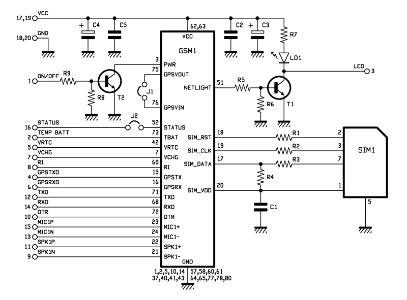
The roles of capacitors C1, C4, and C5 in a circuit may not be immediately clear. Capacitors on the power rail help to smooth out the signal by reducing current ripple, which can be observed using an oscilloscope. Resistors...
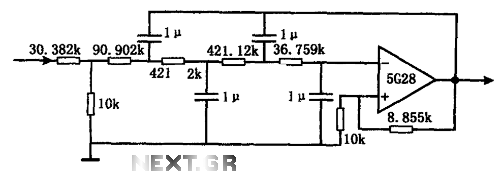
The circuit illustrated in the figure represents a staggered low-frequency active filter. This is a fourth-order Butterworth low-pass active filter designed to filter very low frequency (VLF) random pulse noise voltage at the DC level. The cut-off frequency is...
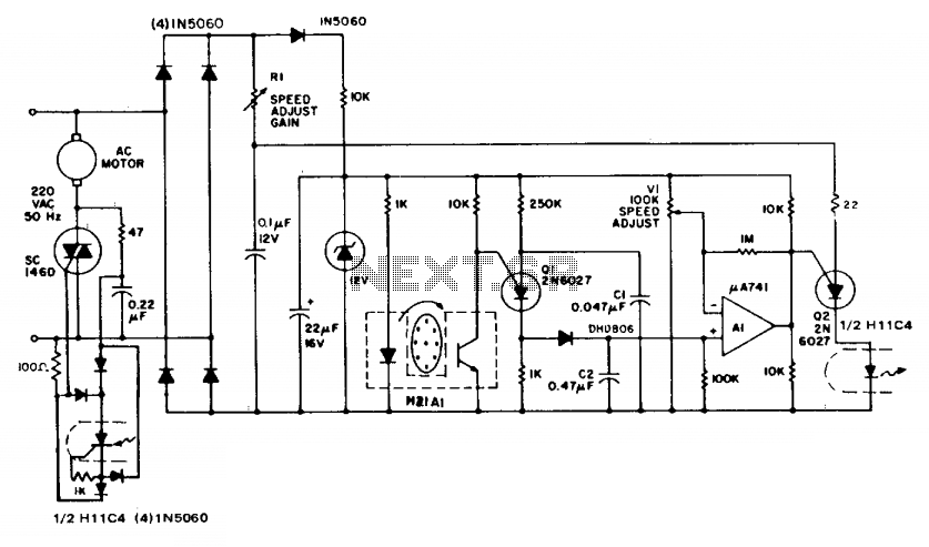
The circuit demonstrates feedback speed regulation for a standard AC induction motor, a task that is typically challenging to achieve without the use of an expensive generator-type precision tachometer. When the apertured disc connected to the motor shaft allows...
Connect the two sections of the variable capacitor (C3) in series to linearize the tuning somewhat. Use the connections on either end of C3 and do not use the middle lead. The gain is sufficient to drive an earphone....