
Stepper Motor Controller
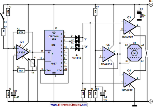
To drive the windings of a stepper motor, a pair of push-pull circuits for each winding, known as an H bridge, is commonly employed. This configuration allows for reversing the current direction through each winding, essential for the operation of a bipolar motor (with windings that lack center taps). The circuit can also effectively drive a unipolar motor (with center-tapped windings). Instead of traditional push-pull circuits, audio amplifier ICs (TDA2030) are utilized in this design. The TDA2030 functions as a power operational amplifier, featuring a difference amplifier at the input and a push-pull driver stage at the output. IC3, IC4, and IC5 are all TDA2030s, with IC3 and IC4 configured as comparators. Their non-inverting inputs are driven by the I and Q signals, while their inverting inputs are set to half the supply voltage, provided by IC5. The outputs of IC3 and IC4 track their non-inverting inputs, each driving one motor winding. The opposite ends of the windings connect to half the supply voltage from IC5. Consequently, one end of each winding alternates between 0 V and a voltage close to the supply voltage, while the other end remains at half the supply voltage. This arrangement ensures that a voltage equal to half the supply voltage is always applied to each winding, alternating in polarity according to the I and Q signals, which is ideal for driving a bipolar stepper motor.
The RPM can be varied using potentiometer P1, although the actual speed varies with each motor type due to differences in steps per revolution. The prototype motor advanced approximately 9° per step, with speed adjustable over a range of about 2 to 10 seconds per revolution. The desired speed can be further adjusted by changing the value of capacitor C1, provided the motor can accommodate the speed. The adjustment range of P1 can be extended by reducing the value of resistor R5, with the range being 1:(1000 + R5)/R5, where R5 is specified in kilohms. If the stepper motor is powered off, it may continue turning due to inertia or mechanical load, leading to potential misalignment between the motor's position and the I and Q signals upon power-up. This can cause the motor to step in the wrong direction initially. To mitigate this, an optional switch S1 and a 1-k resistor can be added to start and stop the motor. When S1 is closed, the clock signal halts, but IC2 retains its output levels, allowing continuous currents through the motor windings to magnetically lock the rotor in position. The TDA2030 includes internal over-temperature protection, reducing output current if the IC overheats. Therefore, it is advisable to attach IC3, IC4, and IC5 to a heat sink, potentially a shared one, when operating with a relatively high-power motor. The TO220 case's tab is electrically bonded to the negative supply voltage pin, allowing the ICs to be mounted on a shared heat sink without the need for insulating washers.Stepper motors are available in several versions and sizes with a variety of operating voltages. The advantage of this general-purpose controller is that is can be used with a wide range of operating voltages, from approximately 5 V to 18 V. It can drive the motor with a peak voltage equal to half the supply voltage, so it can easily handle steppe
r motors designed for voltages between 2. 5 V and 9 V. The circuit can also supply motor currents up to 3. 5 A, which means it can be used to drive relatively large motors. The circuit is also short-circuit proof and has built-in over temperature protection. Two signals are required for driving a stepper motor. In logical terms, they constitute a Grey code, which means they are two square-wave signals with the same frequency but a constant phase difference of 90 degrees. IC1 generates a square-wave signal with a frequency that can be set using potentiometer P1. This frequency determines the rpm of the stepper motor. The Grey code is generated by a decimal counter in the form of a 4017. Outputs Q0 Q9 of the counter go high in succession in response to the rising edges of the clock signal.
The Grey code can be generated from the outputs by using two OR gates, which are formed here using two diodes and a resistor for each gate, to produce the I and Q signals. Here I` stands for in-phase` and Q` for quadrature`, which means it has a 90-degree phase offset from the I signal.
It is common practice to drive the windings of a stepper motor using a pair of push-pull circuits for each winding, which is called an H bridge`. That makes it possible to reverse the direction of the current through each winding, which is necessary for proper operation of a bipolar motor (one whose windings do not have centre taps).
Of course, it can also be used to properly drive a unipolar motor (with centre-tapped windings). Instead of using a push-pull circuit of this sort, here we decided to use audio amplifier ICs (type TDA2030), even though that may sound a bit strange. In functional terms, the TDA2030 is actually a sort of power opamp. It has a difference amplifier at the input and a push-pull driver stage at the output. IC3, IC4 and IC5 are all of this type (which is economically priced). Here IC3 and IC4 are wired as comparators. Their non-inverting inputs are driven by the previously mentioned I and Q signals, with the inverting inputs set to a potential equal to half the supply voltage.
That potential is supplied by the third TDA2030. The outputs of IC3 and IC4 thus track their non-inverting inputs, and each of them drives one motor winding. The other ends of the windings are in turn connected to half the supply voltage, provided by IC5. As one end of each winding is connected to a square-wave signal that alternates between 0 V and a potential close to the supply voltage, while the other end is at half the supply voltage, a voltage equal to half the supply voltage is always applied to each winding, but it alternates in polarity according to the states of the I and Q signals.
That`s exactly what we want for driving a bipolar stepper motor. The rpm can be varied using potentiometer P1, but the actual speed is different for each type of motor because it depends on the number of steps per revolution. The motor used in the prototype advanced by approximately 9 ° per step, and its speed could be adjusted over a range of approximately 2 to 10 seconds per revolution.
In principle, any desired speed can be obtained by adjusting the value of C1, as long as the motor can handle it. The adjustment range of P1 can be increased by reducing the value of resistor R5. The adjustment range is 1:(1000 + R5)/R5, where R5 is given in k. If a stepper motor is switched off by removing the supply voltage from the circuit, it`s possible for the motor to continue turning a certain amount due to its own inertia or the mechanical load on the motor (flywheel effect).
It`s also possible for the position of the motor to disagree with the states of the I and Q signals when power is first applied to the circuit. As a result, the motor can sometimes get confused` when starting up, with the result that it takes a step in the wrong direction before starting to move in direction defined by the drive signals.
These effects can be avoided by adding the optional switch S1 and a 1-k resistor, which can then be used to start and stop the motor. When S1 is closed, the clock signal stops but IC2 retains its output levels at that moment, so the continuous currents through the motor windings magnetically lock` the rotor in position.
The TDA2030 has internal over temperature protection, so the output current will be reduced automatically if the IC becomes too hot. For that reason, it is recommended to fit IC3, IC4 and IC5 to a heat sink (possibly a shared heat sink) when a relatively high-power motor is used.
The tab of the TO220 case is electrically bonded to the negative supply voltage pin, so the ICs can be attached to a shared heat sink without using insulating washers. 🔗 External reference
Related Circuits
A buzzer circuit utilizes a PIC microcontroller to drive a piezo buzzer. The microcontroller is a low-power processor that is ideal for portable and compact devices where battery conservation is essential. The buzzer circuit employs a PIC microcontroller, which serves...

The Atmega8 microcontroller from Atmel features numerous digital and analog input/output lines, making it an ideal choice for developing various measurement equipment. It is essential to have the GCC AVR programming environment installed, as outlined in the article "Programming...
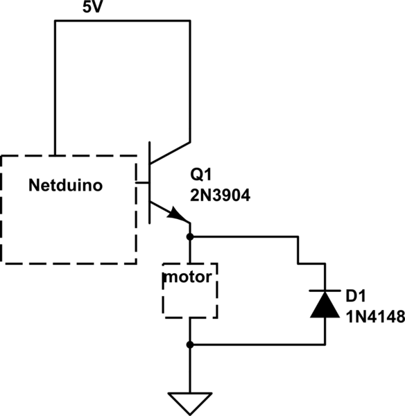
When the motor is connected in this manner, the Netduino activates the transistor, but nothing occurs. Swapping the motor with an LED results in the LED lighting up, indicating that the motor is not receiving sufficient power. Connecting the...
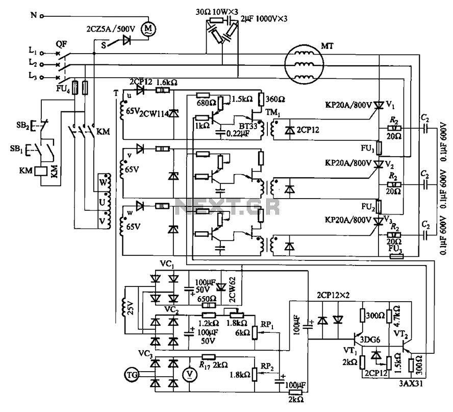
The circuit depicted in Figure 3-181 comprises three thyristors, labeled V1 to V3. The trigger circuit utilizes a single-junction transistor relaxation oscillator. The speed control circuit incorporates negative feedback. A master adjust potentiometer, designated as RPi, is used to...
PID-Control with 68HC11. STEPPER CONTROL. 68HC11 read encoder. High accuracy RPM-measurement with 68HC11. The encoder is connected to PORTA PA0 and PA1. The board must be in BOOTSTRAP MODE (tested with Loggyboard). The circuit utilizes a 68HC11 microcontroller for implementing...
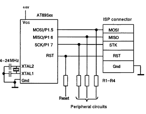
The AT89C family of microcontrollers features a parallel programming interface for flash memory. To write information, a programming voltage of 12V is required, and nearly all pins of the ports are utilized for this purpose. Consequently, parallel programming is...