
Line Following Robot
Modifying servomotors involves a systematic approach to disassembly and reconfiguration of the internal components. The initial step is to unscrew the four screws that hold the servo casing together, which typically requires a small Phillips screwdriver. After removing the screws, the servo can be gently pried apart to access the internal mechanism.
Once disassembled, attention should be directed towards the electronic components housed within the servo. It is essential to carefully detach these components while ensuring that the wiring remains intact for future modifications. The wires are crucial as they will connect the modified servo to a control system or microcontroller.
After the electronics have been removed, modifications can be made to enhance the performance of the servomotor. This may include upgrading the motor for better torque or speed, altering the feedback mechanism, or integrating new control circuitry. It is critical to ensure that any modifications align with the intended application of the servomotor, whether it be for robotics, automation, or other applications.
Once modifications are complete, the servo should be reassembled, ensuring that all components fit securely within the casing. The final step involves testing the modified servomotor to verify that it operates as intended and meets the desired specifications. Proper testing will help identify any issues that may arise from the modifications and allow for further adjustments if necessary.How to Mod the Servomotors (look at the pictures) Remove the four screws from the servo and take it all apart. Remove the electronics keeping only the wires from th.. 🔗 External reference
Related Circuits
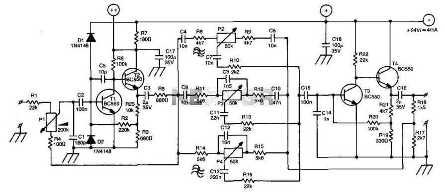
A line amplifier is a valuable component for matching line signals or increasing their levels. This functionality is essential during recording sessions or in public-address systems. Additionally, multiple line amplifiers can be combined to create a line mixer. The amplifier's...
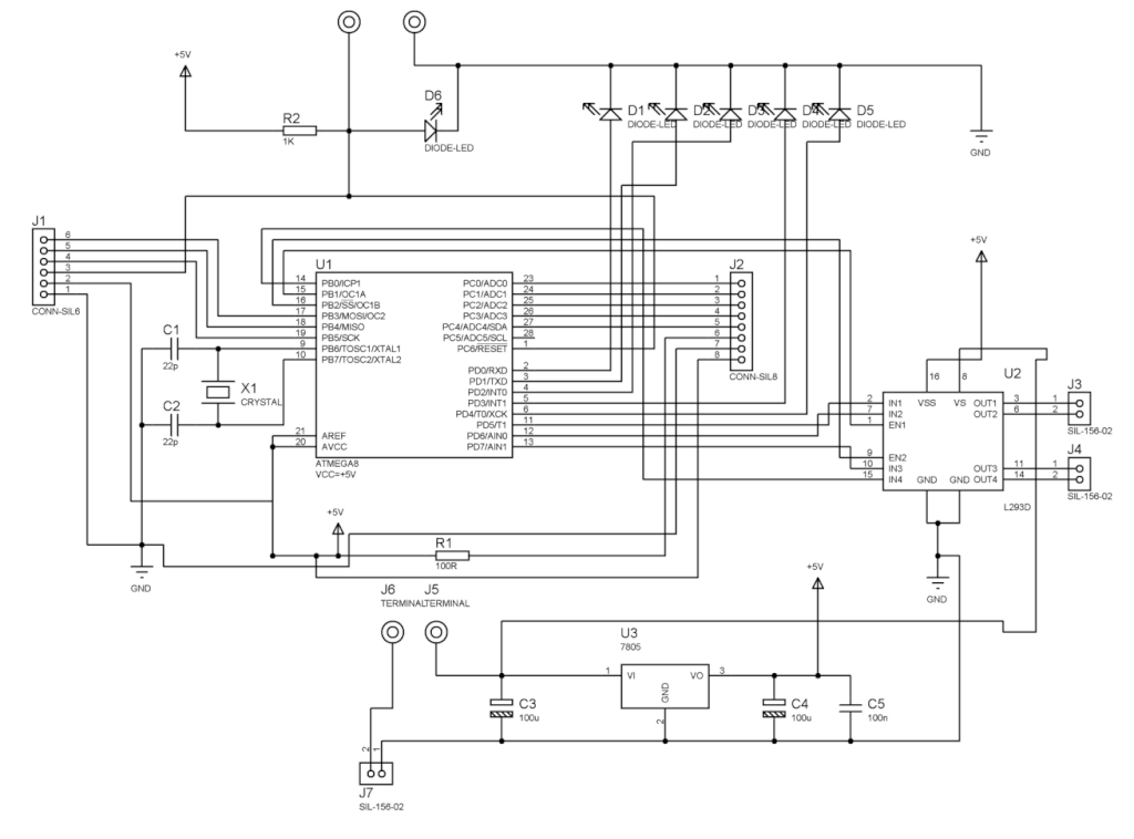
The basic circuit using the L293 forms an H-Bridge driver, as shown in Figure 1, is designed for controlling inductive loads like DC motors. External diodes are necessary for suppressing back EMF. The MiniBoard utilizes the L293D, which features...
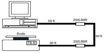
This is the schematic diagram of a 9-Pin RS232 Line Booster Signal Direction. The device functions as a 9-pin RS-232 repeater, re-transmitting all 8 signals while also maintaining the ground line. The 9-Pin RS232 Line Booster is designed to extend...
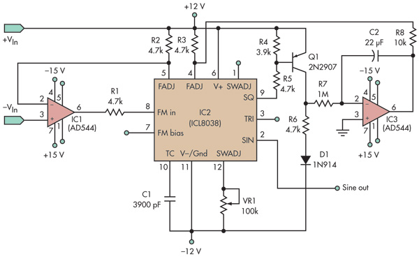
This basic voltage-controlled oscillator (VCO) and waveform generator integrated circuit (IC) circuit features a voltage follower loop (formed with IC1) and a symmetry feedback loop (IC3) designed to eliminate asymmetric duty cycles that can lead to distortion at low...
The National Semiconductor LMV225 is a linear RF power meter integrated circuit (IC) housed in a surface-mount device (SMD) package. It operates within a frequency range of 450 MHz to 2000 MHz and requires only four external components for...
If the sensor system requires an active supply, a single pair of cables can be utilized to transmit both the power supply and the output signal. This approach simplifies the overall system. In sensor systems that necessitate an active power...
Warning: include(partials/cookie-banner.php): Failed to open stream: Permission denied in /var/www/html/nextgr/view-circuit.php on line 713
Warning: include(): Failed opening 'partials/cookie-banner.php' for inclusion (include_path='.:/usr/share/php') in /var/www/html/nextgr/view-circuit.php on line 713